¶ Installation Tutorial Guide
 |
 |
|
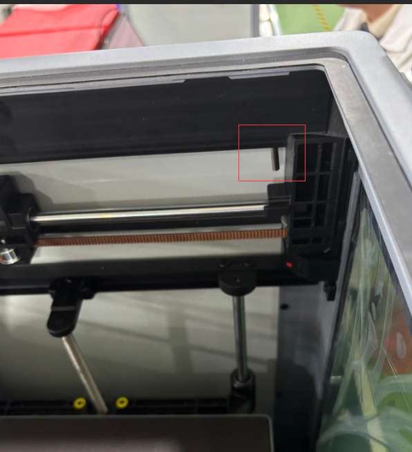
Case temperature sensor installation position before optimization |
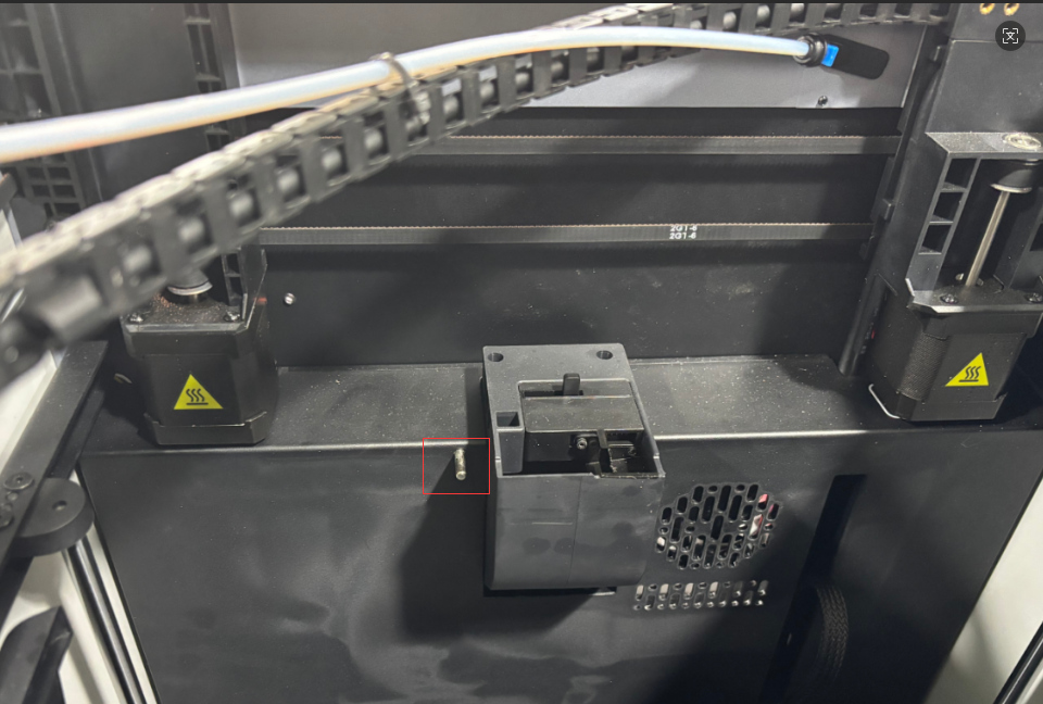
Case temperature sensor installation position after optimization |
¶ Required tools and materials
Tools: 1. H2.0, H2.5 Allen wrench 2. Tweezers
Materials: (Sensor extension cable, temperature sensor, host computer guard) components
-0.jpg) |
⚠️Warm reminder⚠️
Operating Precautions
1. Power-off procedure: Before disconnecting terminals, ensure the power supply is completely disconnected. Power-on operation may cause cascading damage to the lower-level machine's mainboard.
2. Special tool specification, use tweezers for operation. When operating, you need to gently pry open and pull out, and it is forbidden to use brute force to pull. Violent operation will cause:
- Terminal lead damage
- Seat falling off/damage
- Poor contact causes short circuit
¶ Remove the top frame guard plate
1. Use a H2.0 Allen wrench to remove the 3 M3*4 semi-circular head screws at the bottom of the upper computer guard plate, and remove the old guard plate. As shown in the figure.
-2.png)
|
2. Use a H2.5 Allen wrench to remove the 2 HB3*16 hexagon socket head flat tail self-tapping screws from the drag chain base. As shown in the figure
-5.png) |
¶ Remove the cover plate
1. Remove the activated carbon component
The activated carbon component is adsorbed by magnets, just pull it out (in the direction of the arrow in the figure)
-7.jpg) |
2. Use a H2.0 Allen wrench to remove the rear cover plate(Note: This process involves two types of screws, please distinguish them and place them in different areas to avoid mistakes.)
As shown in the figure: Remove the 2 self-tapping screws and 8 machine screws on the rear cover plate in order. Remove the rear cover.
-8.jpg) |
-9.jpg) |
3. Use tweezers to remove the old temperature control sensor terminal. As shown in the figure: a Remove the old temperature control sensor as well. As shown in the figure: b
-10.png)
|
-12.png)
|
¶ Installation (sensor extension cable, temperature sensor, upper computer guard plate) assembly
1. Install the (sensor extension cable, temperature sensor, upper computer guard plate) assembly into the right edge slot of the top frame. As shown in the figure.
Note: Upgrade the AP board algorithm software before installation
-15.png) |
2. Use a H2.0 Allen wrench to tighten the 3 M3*4 screws on the guard plate. (Note: When installing, 2/3 of the metal shell of the temperature sensor is exposed, and the appearance is tilted, but the measured temperature is accurate. It does not affect printing and the temperature detection effect in the machine chamber.) As shown in the figure.
-16.png) |
3. Insert the extension cable of the sensor into the wiring slot of the X-axis motor base on the lower right side of the drag chain base for wiring. Install the drag chain base. (Note: When installing the drag chain base, pay attention to the extruder cable inside the drag chain base). As shown in Figure: a and tighten the HB3*16 screws. As shown in Figure: b
-17.png)
|
-18.png)
|
4. Lead the extension cable into the wiring trough of the electrical box. Insert the temperature sensor terminal into the temperature control socket in the lower computer motherboard box. As shown in the figure
-23.jpg) |
Install the rear cover
Note for installing the rear cover: Avoid the Teflon PTFE tube.
First, install the rear cover plate from above, aligning it with the boat-shaped switch hole. Use a H2.0 Allen wrench to tighten the 8 machine screws and 2 self-tapping screws on the rear cover. As shown in the figure:
-24.jpg) |
-25.jpg) |
Optimize the above operation steps. If you have any questions or need help, please contact us by email: support@artillery3d.com After-sales service.