*** Warm tips ***
Operational considerations
1. Power-off procedures
- Power must be completely disconnected before hot-plugging the terminal.
- Powering on may burn the tool head small board and cause cascading damage to the main control board.
2. Special tool specifications
- Use tweezers for operation.
- When operating, gently pry out; do not pull forcibly.
- Violent operation will cause:
⚫Terminal lead damage
⚫ Seat detachment/damage
⚫ Short circuit caused by poor contact
3. Warranty Terms
- The following damages caused by improper operation are not covered by warranty:
⚫ Seat detachment/deformation
⚫ Terminal lead fracture
⚫ Tool-head PCB burn
⚫ Mainboard failure of the lower-level controller
4. Parts procurement channels
Official parts can be purchased through “https://www.artillery.com”
It is recommended to use OEM parts to ensure compatibility.
¶ Maintain tool head components; frequently troubleshooting temperature anomalies.
 |
 |
|
¶ Tools used: 1. tweezers 2. H1.5 internal hex key 3. PH0 Phillips screwdriver
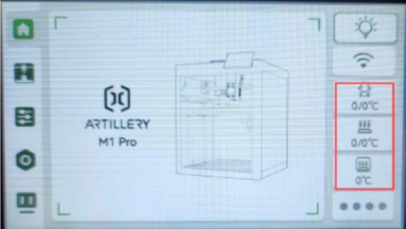
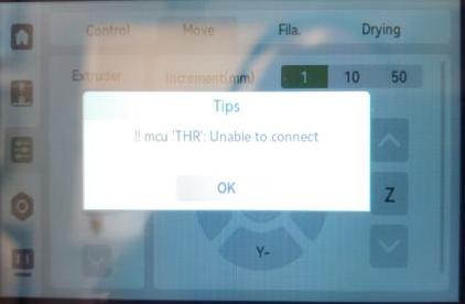
If a firmware update causes the screen temperature to display “0” — perform the upgrade on the screen again; if the temperature “0” and THR still appear, you can download
the image file from the official site: https://wiki.artillery3d.com/en/m1
Flash the PC/mainboard image to fix the issue.
Visit the official site https://wiki.artillery3d.com/m1/manual/flashing-guide USB-OTG flashing guide.
Operation:
If the nut fixing the small board cable connector on the tool head is damaged — please go to the official site: https://www.artillery3d.com/collections/spare-parts-for-m1-series
Purchase a tool head small board to fix the issue.
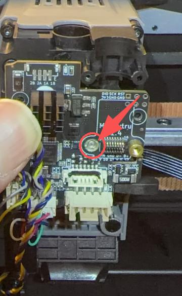 |
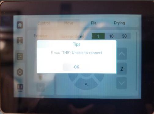
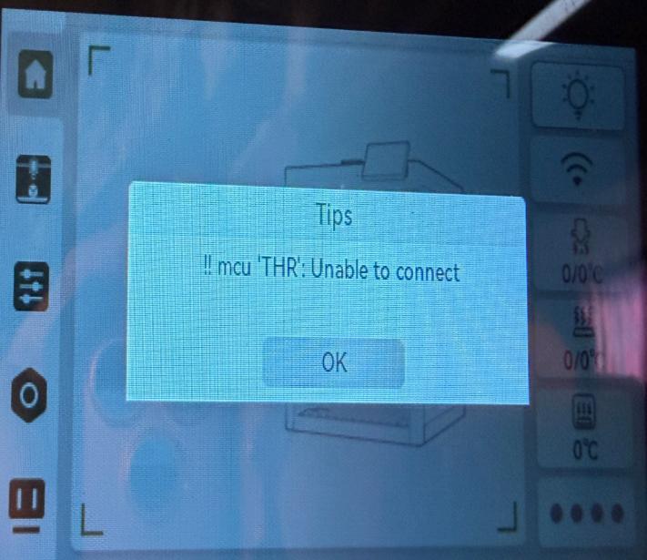
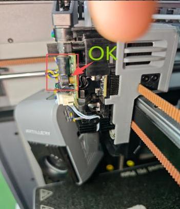
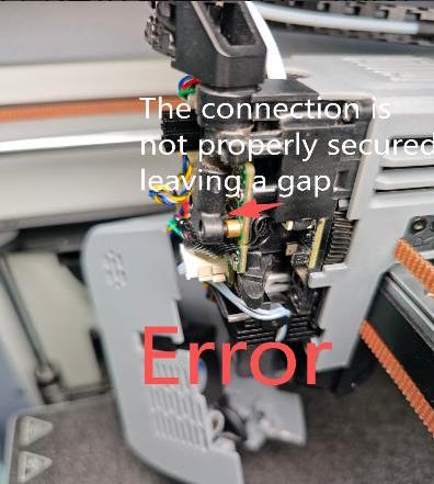
1.After replacing with a new tool head small board, if the temperature display still shows “0” and mcu ‘THR’ — please check whether the cable terminals are properly connected. Figure a is correct. Figure b shows the cable connector not seated properly, leading to poor contact and errors.
 |
 |
 |
|
Figure: a |
Figure: b |
|
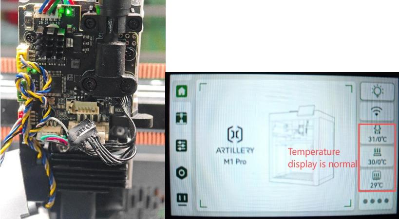
2.Please power off, unplug the material cut-off and blade connection ribbon ends, then power on again to check if the screen can display the temperature normally. If removing the connection as shown in the figure allows normal temperature display, it indicates an abnormality in the material cut-off and blade small board. (Please check the pins and cables of the material cut-off and blade small board connector seats)
 |
 |
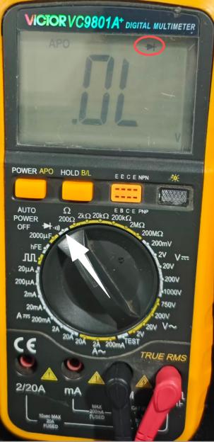
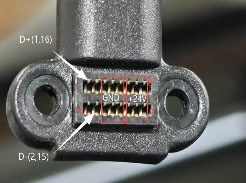
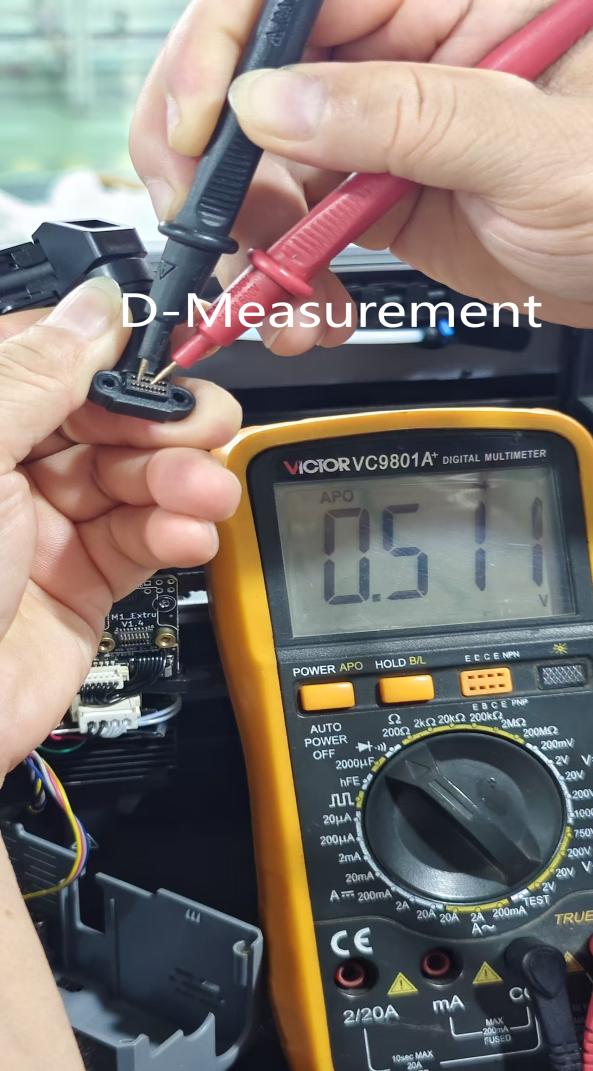
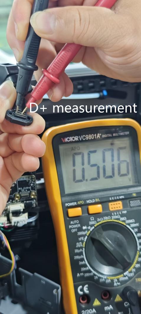
¶ If powered hot-swapping operations that disconnect the hot end and fan terminals cause temperature display “0” and MCU ‘THR’ abnormality — please power off, remove the cable from the tool head, use a multimeter set to the buzzer/diode range and switch to diode range to measure the data lines (D+ D−) on the cable to see if the GND parameter is normal.
1. If the value decreases (parameter: 0 V - 0.46 V), it indicates the mainboard of the host controller is damaged during powered operation — go to the official site https://www.artillery3d.com/collections/spare-parts-for-m1series to purchase an MC board (main control board) to fix the issue.
2. If the value becomes infinite or intermittent, replace the tool head cable to fix this issue. MCU “THR As shown, the correct measurement: the normal values for (D+ D-) are in the range of 0.50 V to -0.52 V. Note: Please perform measurements with the power off. During measurement, the black probe should measure D+ and D- respectively, with the red probe fixed to GND for the measurement.
 |
 |
 |
 |
If the above steps are all ineffective, please contact our after-sales support at support@artillery3d.com.