¶ When do you need to remove the extruder chamber for cleaning, cleaning.
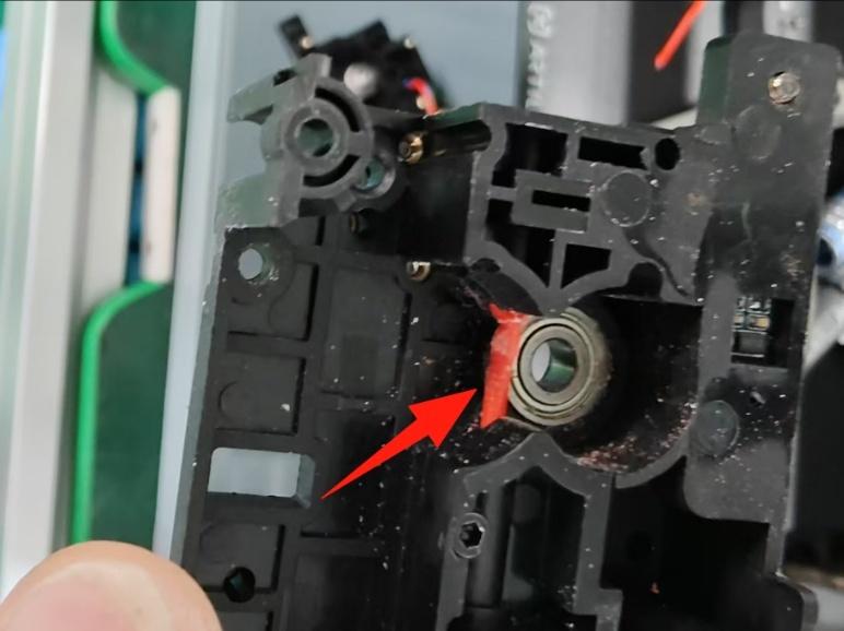
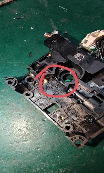
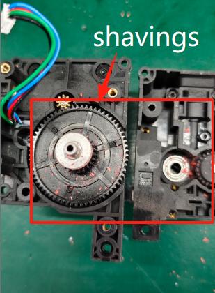
No feed/jamming, plugging, shaving filaments.
As pictured:
 |
 |
 |
The above problems are broadly categorised into the following:
- No feeding/jamming/blocking
① Extruder chamber already exists in the blockage.
② Deformation of the consumable end.
③ The temperature parameter of the slicing model & consumables do not match / wrong consumables are used in the printing process.
④ The temperature of the hot end is out of control.
⑤. The cutter does not spring back.
⑥ Nozzle plugged. - Planing material
① The slicing model temperature parameter is low in relation to the actual print consumable temperature.
② Consumables have been unpacked and stored for too long/expired.
③ Printing silk consumable temperature parameters do not match.
④ Consumables packaging leakage leads to moisture in the consumables.
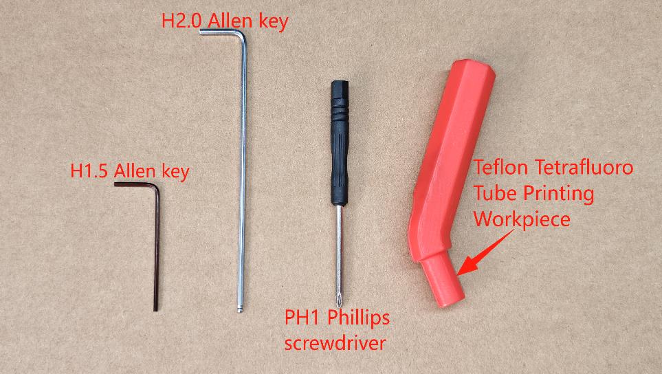
¶ Use of tools
- H1.5&H2.0 hexagonal spanner,
- PH1 Phillips screwdriver,
- Disassembling Teflon Teflon Tetrafluoro Tubes Printed Workpiece.
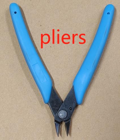
- Scissor Pliers
 |
 |
¶ Safety warnings and machine status before starting operation
Make sure that the printer is not connected to the power supply when performing the removal operation.
Note: Remove the screws on the extruder parts into the screw box for sorting to prevent mistakes.
¶ Extruder disassembly procedure
¶ Step 1 - Remove the cowl
Remove the nozzle cover outward and remove the model fan terminal. (Refer to nozzle cover guide)
¶ Step 2 - Disassemble the Hot End Assembly
Cut off the consumables by pressing the cutter handle with the consumables left in the extruder, remove the 2 M3*10 semi-circular head screws of the hot end assembly with the H2.0 hexagonal spanner, and pull out the terminals of the hot end assembly. (Refer to the guide for replacing the hot end and assembly)
¶ Step 3 - Disassemble the Printhead Cable Wire Connector
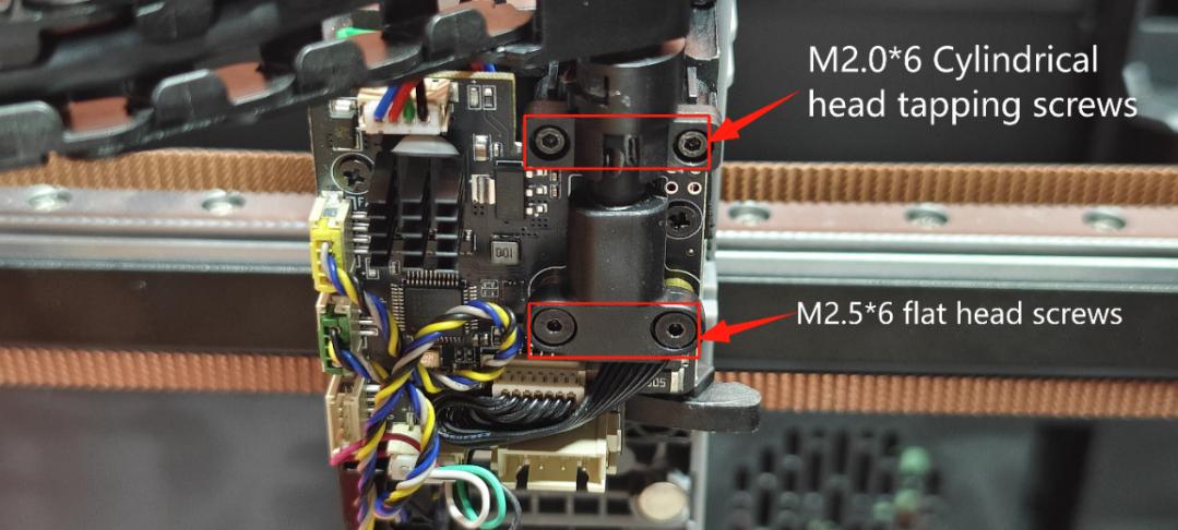
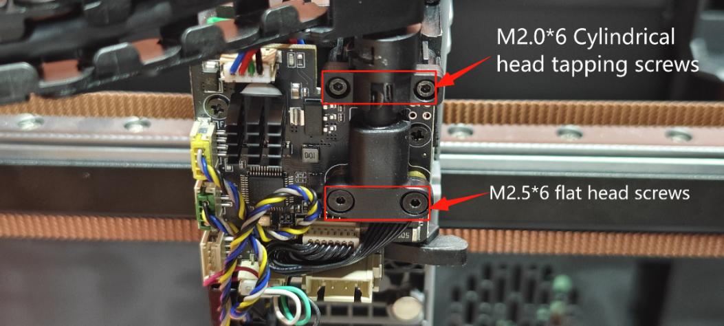
① Remove the cable connector screws with H1.5 hexagonal screwdriver (2 x M2.0*6 cylindrical head tapping screws 2 x M2.5*6 flat head screws)
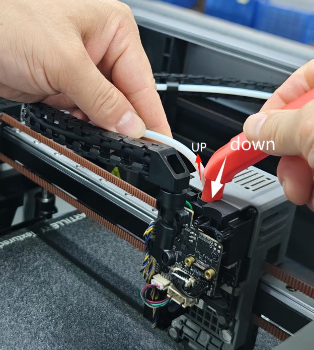
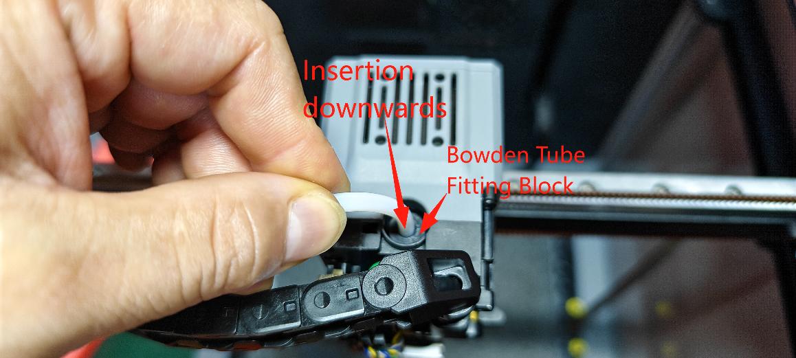
② With the right hand, press down on the extruder Bowden tube fitting seat material tube end with the Remove Teflon Teflon Tetrafluoro Tubing Tooling, and with the left hand, manually pull out the white material tube.
¶ Step 4 - Remove Extruder Set Screws
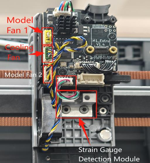
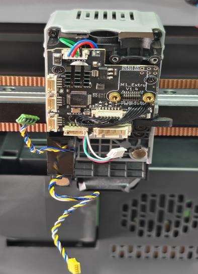
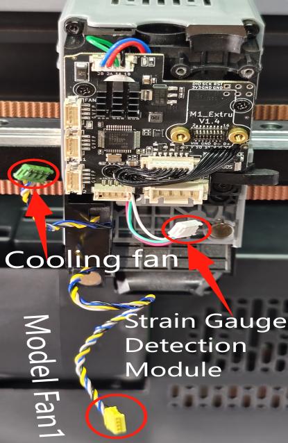
① Remove the hot end cooling fan and the rear end model fan 1, and the strain gauge detection module terminals.
 |
 |
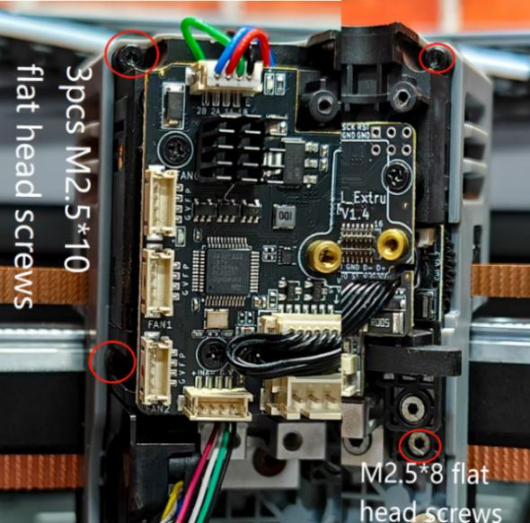
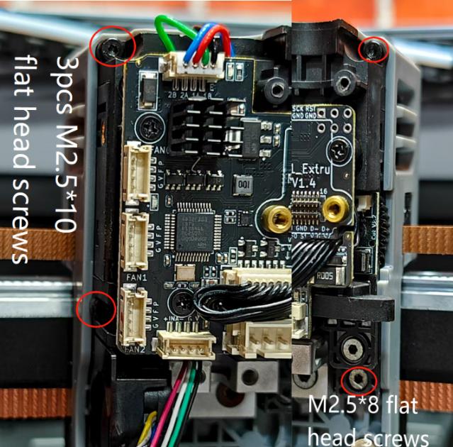
② Remove the 4 fixing screws (3 M2.5*10 flat head screws and 1 M2.5*8 flat head screw) on the extruder with the H1.5 hexagonal spanner. Remove the extruder assembly.
¶ Step 5 - Removing the Extruder Circuit Board
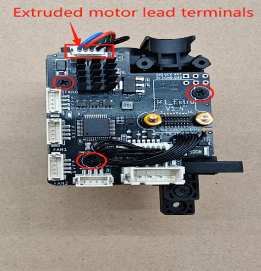
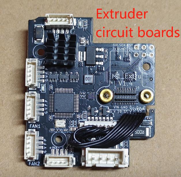
① Remove the 3 M2.0*5 flat head Phillips set screws on the circuit board with a PH1 Phillips screwdriver. Manually pull out the extruded motor terminals.
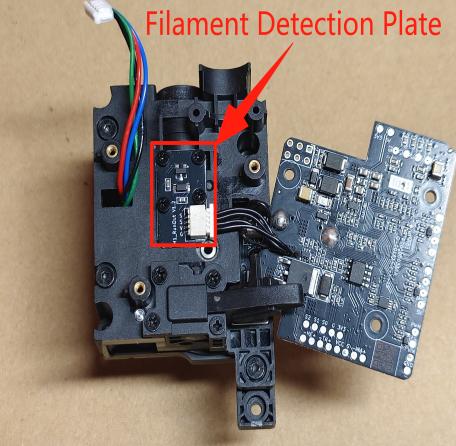
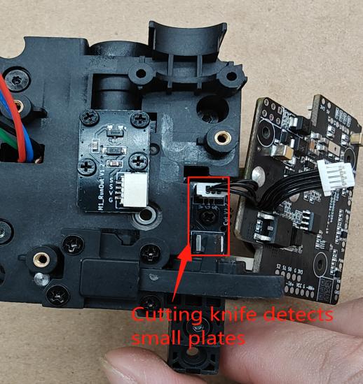
②. Remove the extruder board by turning the board outward to the right and pulling out the terminals for the material wire detection and cutter detection small board wires.
 |
 |
 |
¶ Step 6-Disassembly of Extruder Upper Housing
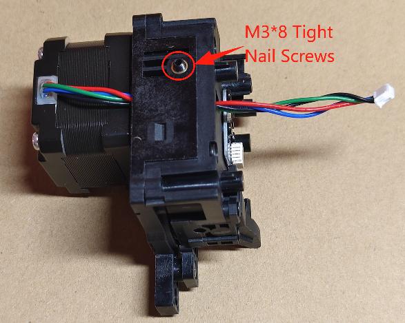
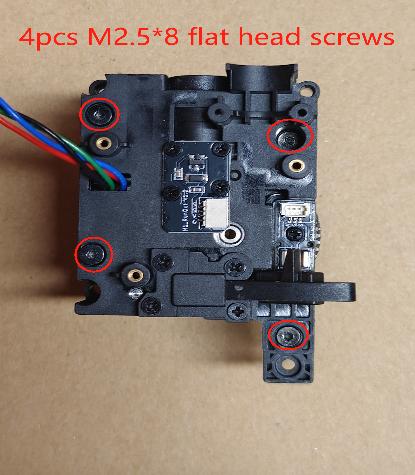
① Use H1.5 hexagonal screwdriver to loosen the side tightening nail screws, and then proceed to remove the 4 M2.5*8 flat head screws from the upper case of the extruder.
 |
 |
② Separate the upper and lower extruder shells slowly in the opposite direction of the arrow in the figure. (Note: Extruder handles, springs and spring retaining brackets in the extruder chamber should not be dropped or lost)
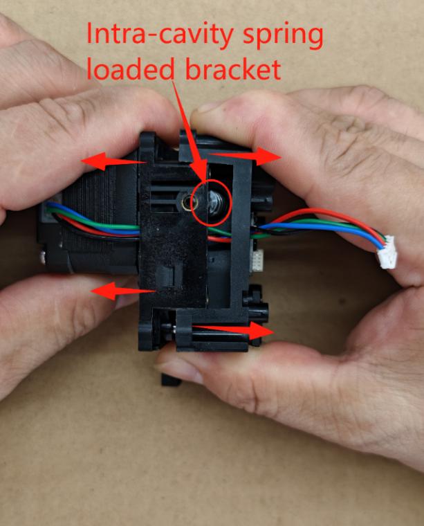
¶ Step 7 - Extruder cavity cleaning
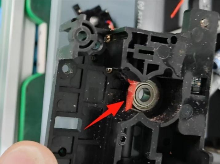
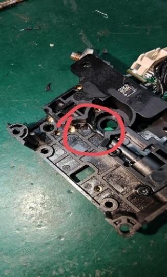
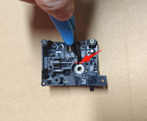
① No feed, jamming, blocking - Use shear pliers to cut and bend the material wire remaining in the extruder to remove it.
 |
 |
 |
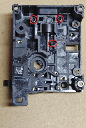
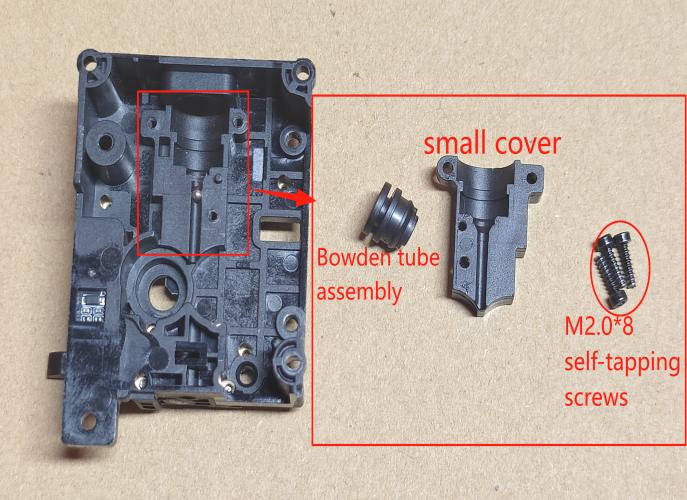
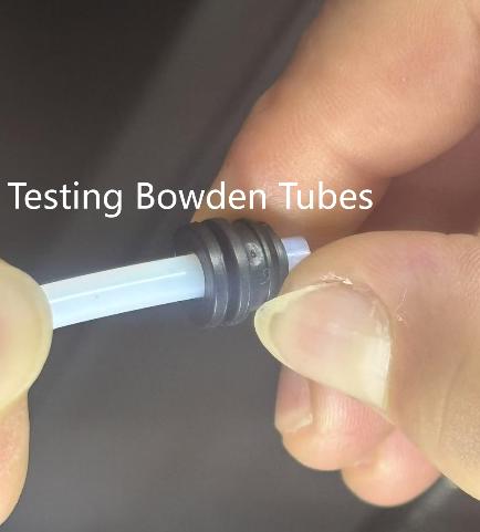
② Remove the small cover plate (3 M2.0*8 cylindrical head self-tapping screws) in the chamber of the extruder's upper case with a H1.5 inner hexagonal spanner and inspect the Bowden tube assembly in the chamber. (Remarks: When to replace the Bowden tube assembly - when jamming the tube (PTFE tube), it is easy to dislodge by pulling with slight force and can be replaced.)
 |
 |
 |
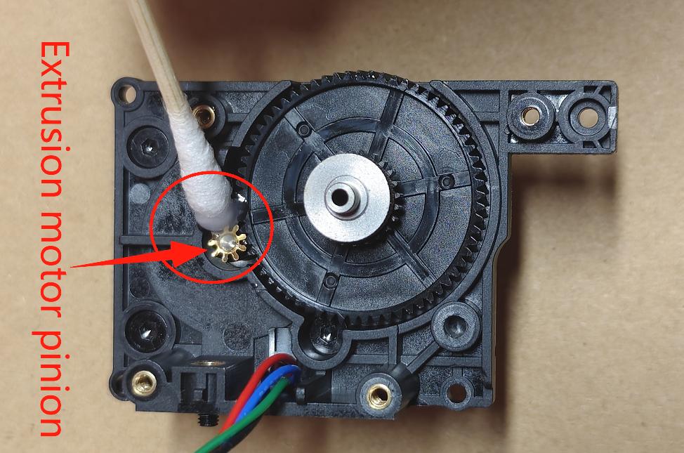
③ Planing material - Clean the extruder chamber with a soft bristle brush. And use a small cotton swab to stick a little grease on the extruder motor pinion.
 |
 |
¶ Step 8 - Extruder Chamber Maintenance
① After 200 hours of use, remove the nozzle cover. Fine-tune the extruder left side tightening nail screw into about 1mm with a H1.5 Allen key.
② After 300 hours of use, disassemble the extruder to clean the inner chamber and apply a small amount of grease to the extruder gears and bearings.
¶ Installation Guide for Extruders
¶ Step 1 - Installation of Extruder Inner Chamber Mechanical Gear Fittings
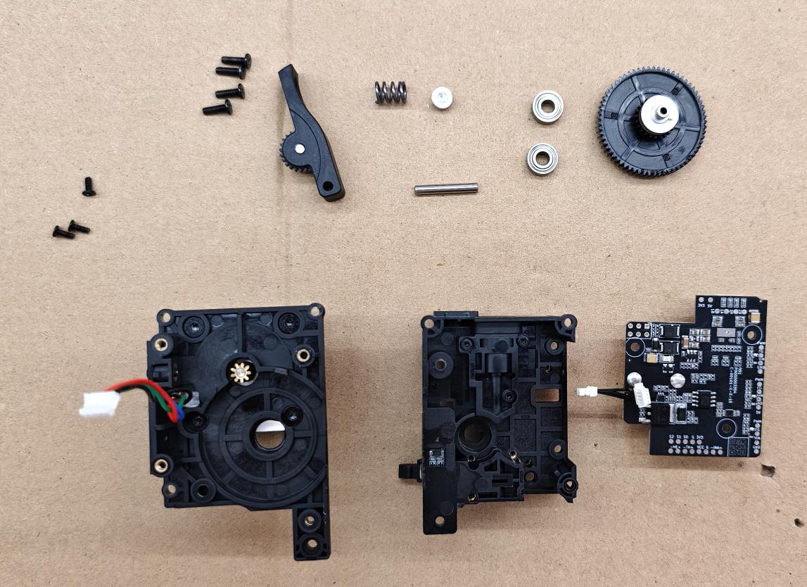
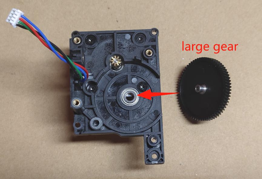
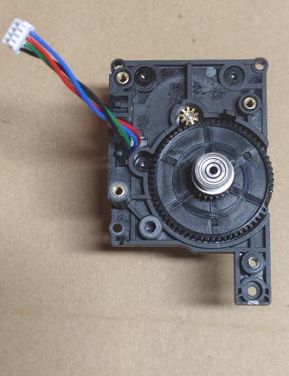
① .Install bearings on both ends of the large gear shaft and install it in the extruded lower case motor gear end position.
 |
 |
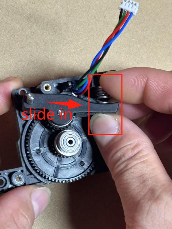
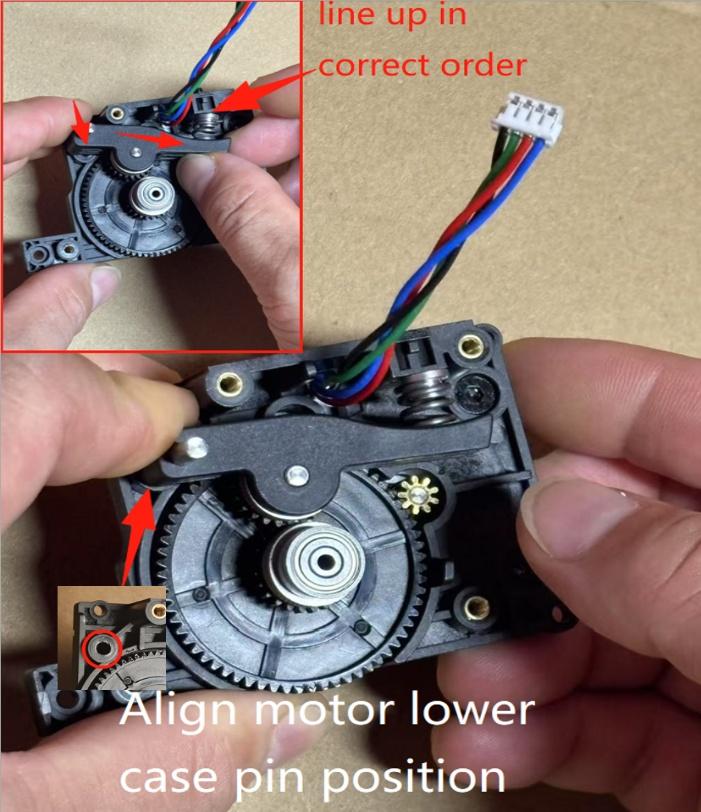
② .Right hand fingers pinch (handle assembly & compression spring, spring holder end) together and snap into place to install until major gear shaft pinion is aligned. Left fingers pinch the handle pin end to align the motor lower case pin position. Right fingers press the spring bracket to align the tightening nail screw position loosely, press the handle pin to the lower case lock fixed.
 |
 |
¶ Step 2 - Installation of Extruder Upper Shell
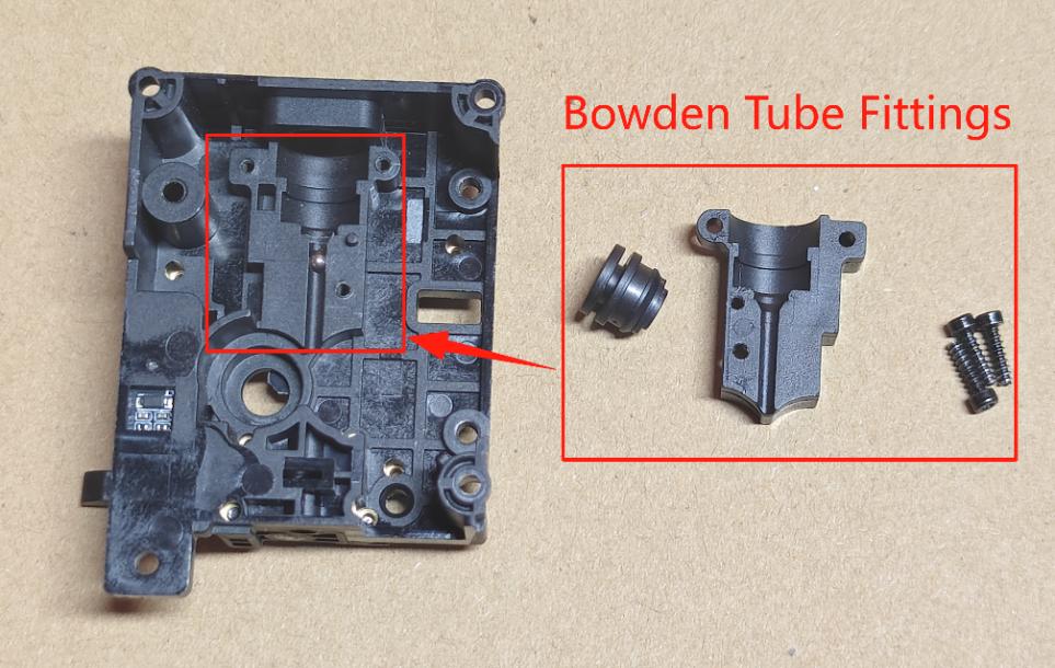
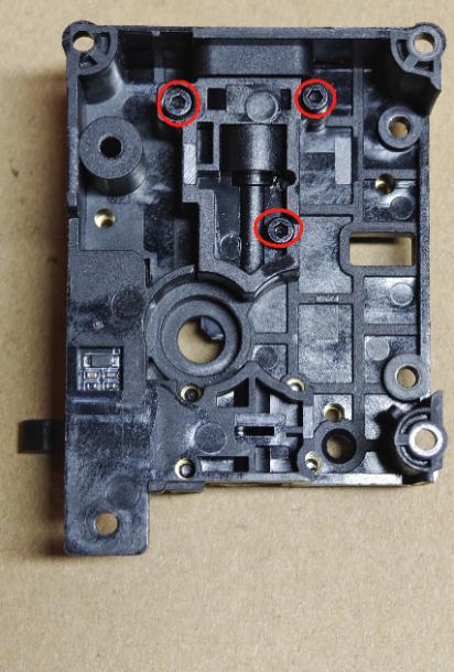
① Assemble the extruder upper shell Bowden tube fittings (Bowden tube assembly, small cover plate), use H1.5 hexagonal spanner to lock the small cover plate with 3 M2.0*8 cylindrical head self-tapping screws.
 |
 |
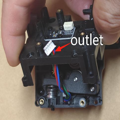
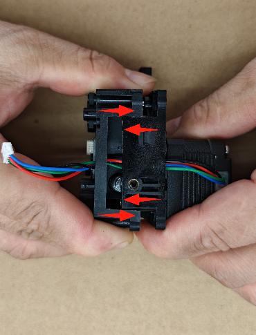
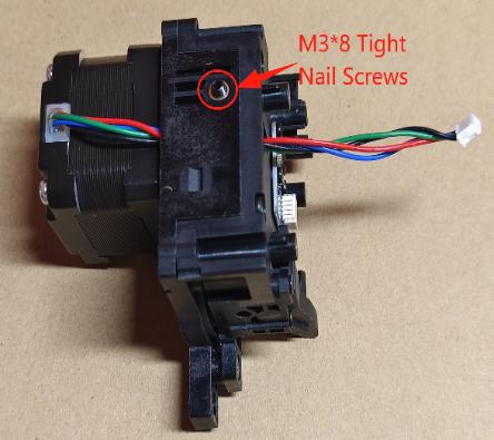
② Assemble the extruder shell - first, put the lower shell motor leads into the upper shell motor outlet, and butt the upper and lower shells to install the compression. Use H1.5 hexagonal spanner to lock the fixing screws (4 M2.0 * 8 flat head self-tapping screws) and the left side of the tightening nail screws to screw the surface of the extruder shell can be flat.
As shown in the picture:
 |
 |
 |
 |
¶ Step 3-Mounting the Extruder Board
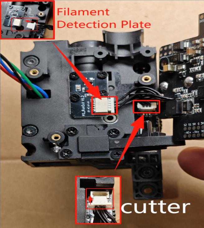
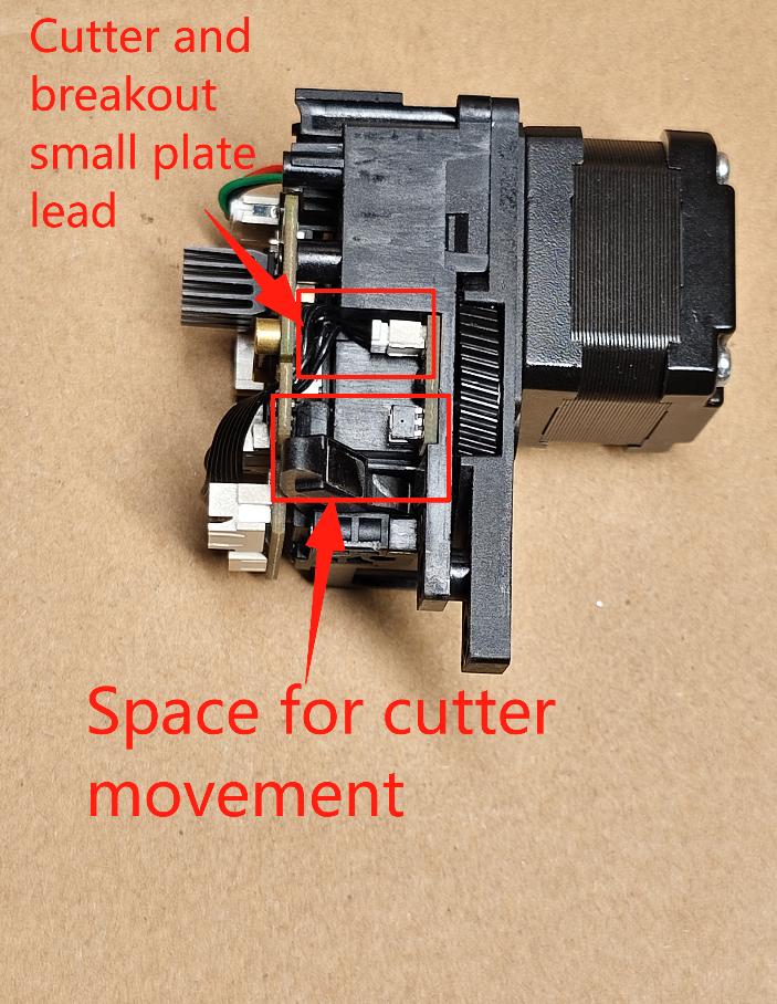
① Align the extruder circuit board lead terminals with the cutter detection (3P terminal) and material breakage detection (4P terminal) small board holder ports (note: the two terminal planes facing the direction of the plug and the number of terminal wires spliced, in order to prevent mistakes). And turn the extruder board to the left.
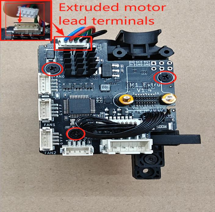
② Install the extruder motor wire terminal into the extruder circuit board motor holder. Use PH1 Phillips screwdriver to lock the extruder circuit board to fix 4 M2.5*5 Phillips flat head screws. And turn the extruder assembly to the left side, check the cutter and break material lead must avoid the cutter handle position. To prevent the cutter cut material function failure.
 |
 |
¶ Step 4 - Install Extruder Set Screws
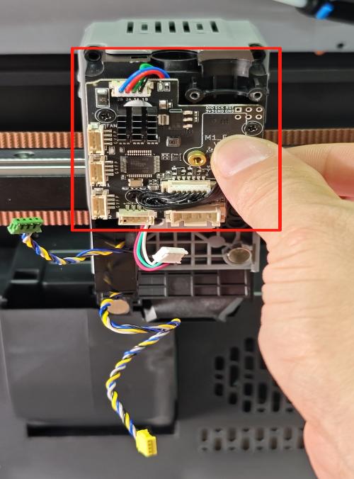
① Install the extruder assembly into the middle frame of the machine nozzle, and lock 3 M2.5*10 flat head screws and 1 M2.5*8 flat head screw with H1.5 hexagonal spanner .
 |
 |
②. Plug the hot-end cooling fan and the rear-end drum fan 1, and the strain gauge detection module terminals correspondingly to the extruded circuit board holders.
 |
 |
¶ Step 5 - Install Extruder Cable Retaining Screws
① Install the cable wire female connector to the extruder circuit board with the male connector and screw posts aligned and inserted. Lock the cable wire connector screws (2 x M2.5* 6 flat head screws 2 x M2.5*6 cylindrical head self-tapping screws) tightly with a H1.5 hexagonal screwdriver.
② Insert the white material tube (Teflon Teflon tube) into the extruder's Bowden tube fitting seat.
¶ Step 6-Installing the Hot End Assembly
Install the hot end assembly terminals to the extruder circuit board holder and lock the hot end assembly 2 M3*10 half-round head screws with H2.0 Allen spanner. (Refer to Replacement of Hot End and Assembly Guide)
¶ Step 7 - Installing the nozzle cover
Plug the nozzle cover model fan terminals correspondingly into the extruder circuit board holder and install the nozzle cover to the extruder. (Refer to the printhead cover guide)