¶ What is a hot bed
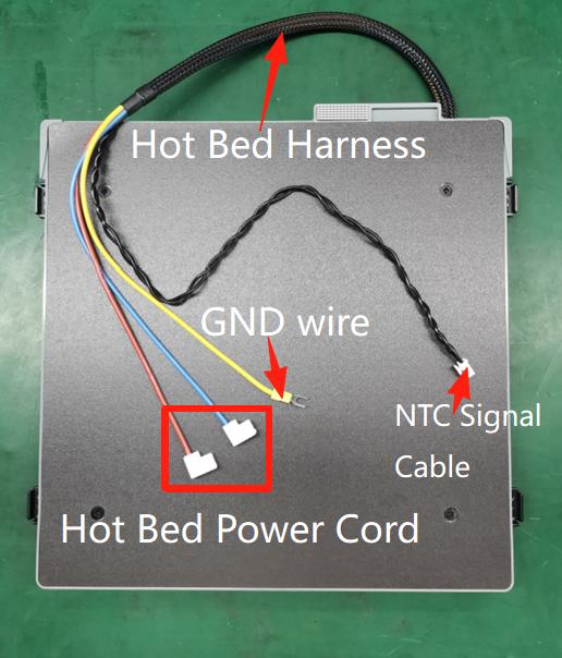
The heat bed of the M1 series printers is a platform installed in the printer chamber that moves up and down along the Z-axis and heats up according to the temperature set by the user. Setting the heat bed temperature at the right level can effectively improve the adhesion of the model to the build plate and prevent the model from warping.
¶ When to Replace
1. The hot bed is not warming up, negative temperature, and the connector has been troubleshot and confirmed to be in normal condition;
2. Physical damage or visible deformation that affects function;
3. It was confirmed by the aftermarket staff that the heat bed needed to be replaced.
¶ Tools and materials required
1. New hot bed components
2. H2.0/H2.5 hexagonal spanner; PH2 Phillips screwdriver
3. Tweezers; Sharp-Nosed Pliers
Safety warnings and machine status before starting operation
Make sure that the printer is not connected to a power source when performing the disassembly operation.
¶ Operation Guide
¶ Step 1 - Adjusting the Heat Bed Position
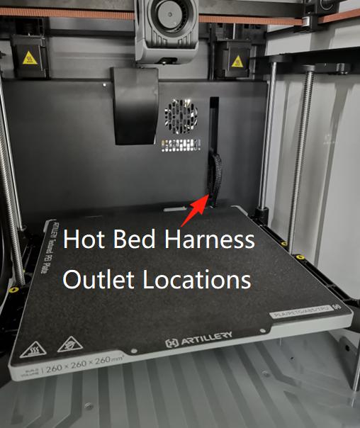
Power on the printer and control the downward movement of the heat bed through the display screen, placing the heat bed against the underside to expose the front of the electrical box where the heat bed wiring harness exits. Then switch off the printer and unplug the power cord and remove the glass top cover.
¶ Step 2 - Remove the Activated Carbon Assembly
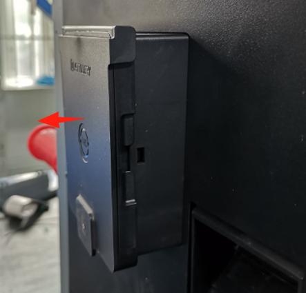
The activated charcoal assembly is magnetised and can be pulled out directly (in the direction of the arrow shown).
¶ Step 3 - Remove the rear cover sheet
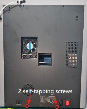
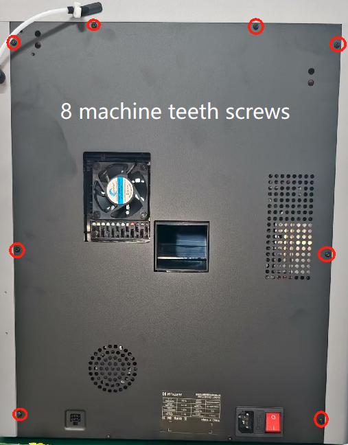
NOTE: There are two types of screws involved in this process, so please keep them separate and put them in different areas so you don't make a mistake. Remove the 2 self-tapping screws on the rear cover sheet metal and the 8 machine threaded screws in the order shown. Remove the rear cover by tilting it towards the lower right corner.
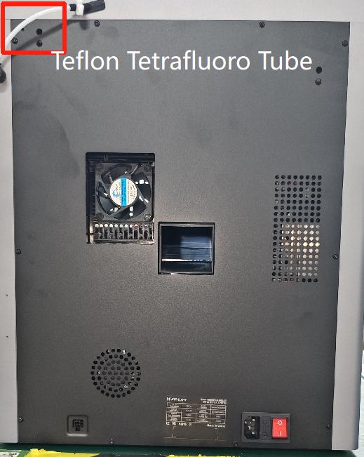
Note: Avoid the Teflon PTFE tubing.
 |
 |
 |
¶ Step 4 - Remove the hot bed harness (electrical box end)
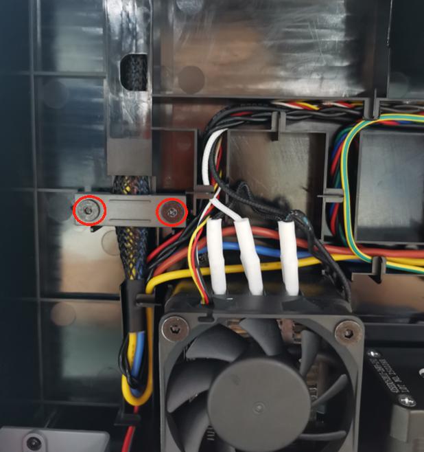
① . Remove the 2 self-tapping screws with an H2.5 Allen key and remove the pressure plate.
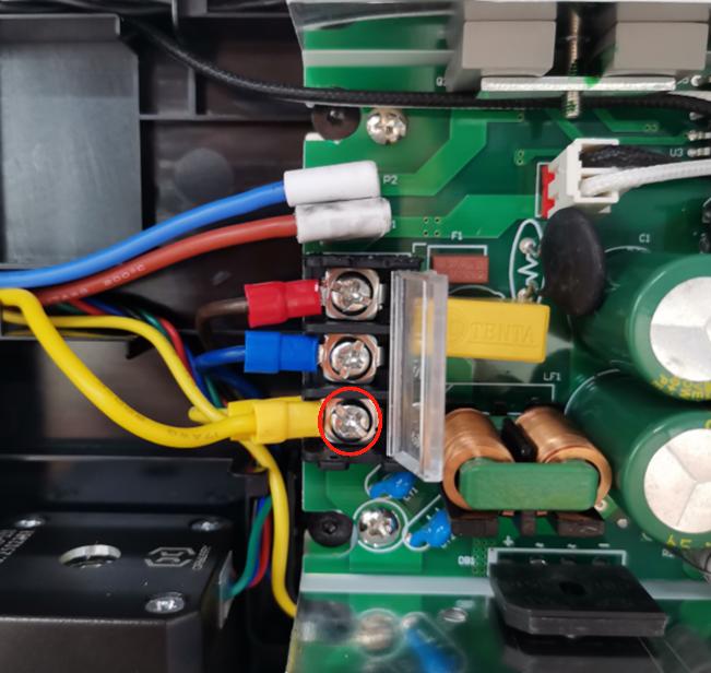
② . Use a PH2 Phillips screwdriver to loosen the power ground compression screw and remove the hot bed ground terminal.
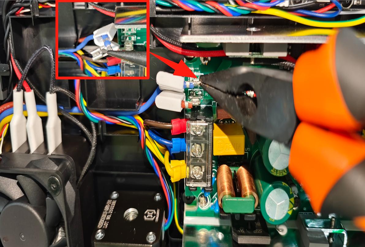
③ . Loosen the white protective rubber sleeve of the power cord terminal of the hot bed and pull out the upper end of the terminal with sharp-nosed pliers to pull out the two power cords
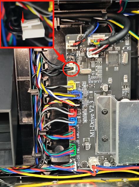
④. Unplug the terminals by pinching the tabs of the hot bed NTC signal wire terminals in the direction of the arrows shown in the illustration.
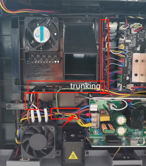
⑤. Remove the hot bed cord from the electrical box cable management slot.
¶ Step 5 - Remove the hot bed assembly
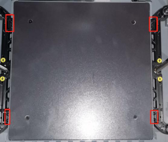
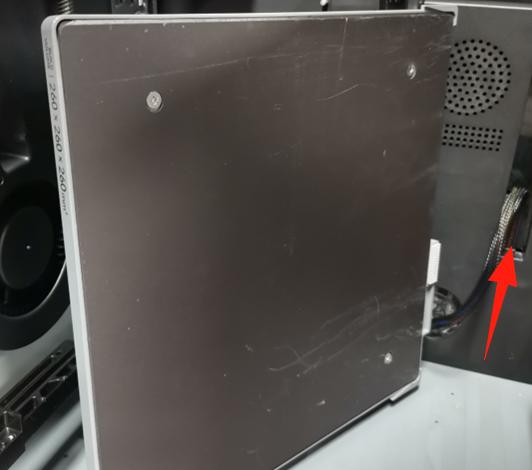
Using an H2.0 Allen spanner, remove the 8 screws holding the sides of the hot bed bracket, move the hot bed assembly and hot bed wiring harness out on the diagonal side, and remove the hot bed assembly from the front of the door.
 |
 |
¶ Step 6 - Disassemble the Hot Bed Assembly
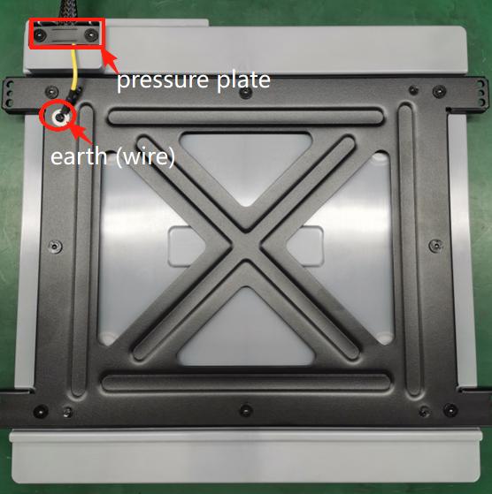
①. The heat bed assembly is placed on the back: Remove the (yellow and green wire) ground screws with the H2.0 Allen key, remove the two screws of the crimp plate alternately in sequence with the H2.5 Allen key, and take out the crimp plate.
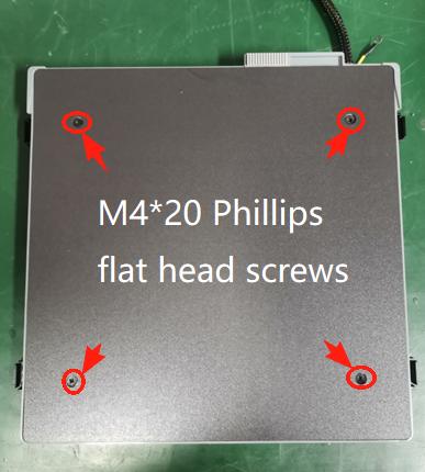
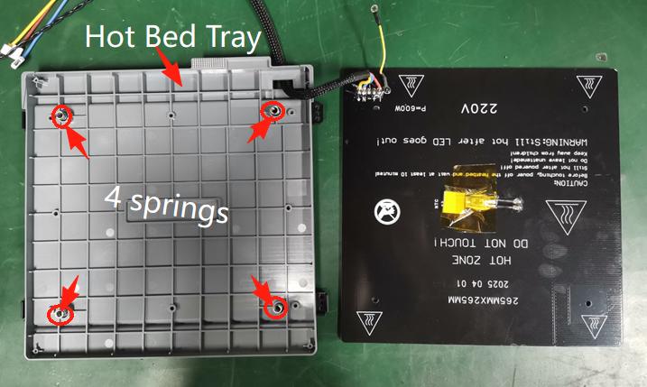
② . The heat bed assembly is placed on its front side: Use a PH2 Phillips screwdriver to remove the 4 M4*20 Phillips flat head screws on the hot bed plate. Then dismantle the heat bed to turn it to the right and remove the heat bed wiring harness (Note: When dismantling the heat bed, retain the 4 springs on the heat bed tray, which do not need to be dismantled).
 |
 |
¶ Installation of hot beds
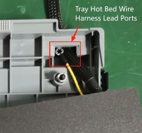
① . The heat bed assembly is placed on its front side: Pass the hot bed harness (NTC signal wire, power wire, earth wire) and the (yellow and green) ground wires on the back of the hot bed through the palletised hot bed harness lead ports in that order. Mount the hot bed to the tray fit and install the M4*20 Phillips flat head screws. Use a PH2 Phillips screwdriver to lock the four M4*20 Phillips flat head screws on the heat bed. (Note: the spring left on the tray must not be missed/fall off).
 |
 |
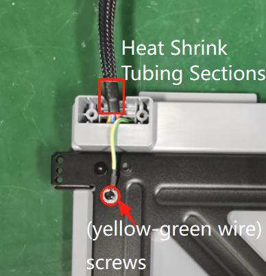
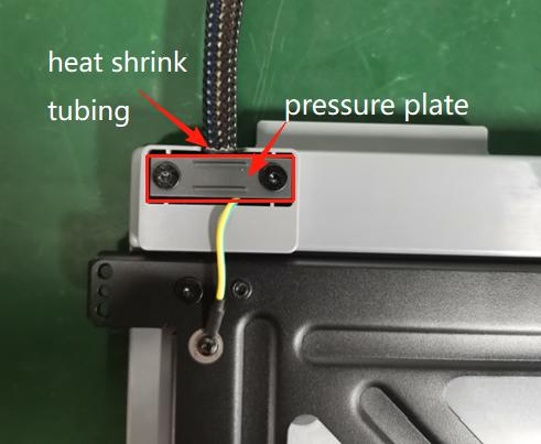
② . The heat bed assembly is placed on the back: Tighten the (yellow-green) ground screw with an H2.0 hexagonal spanner. Place the heat shrink tube portion of the wire harness completely underneath the platen, making sure that the heat shrink tube of the wire harness is not exposed (flush with the tray side extension) and that the wire harness stays straight; lock the two screws of the platen with the H2.5 Allen wrench.
 |
 |
¶ Step 7 - Installing the Heat Bed Assembly
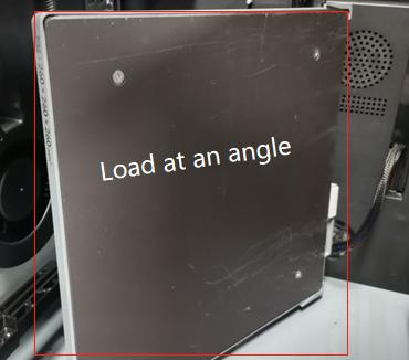
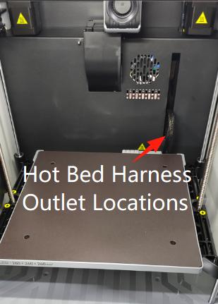
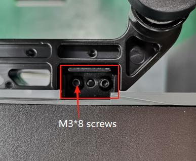
Install the hot bed assembly into the machine cavity from the front tilted and sideways into the machine cavity onto the two side Z sliders centrally placed and thread the wire harness into the hot bed wire outlet of the electrical box. Use an H2.0 Allen key to lock in the 8 screws for fixed locking.
 |
 |
 |
 |
¶ Step 8 - Adjusting the Hot Bed Assembly Harness Position
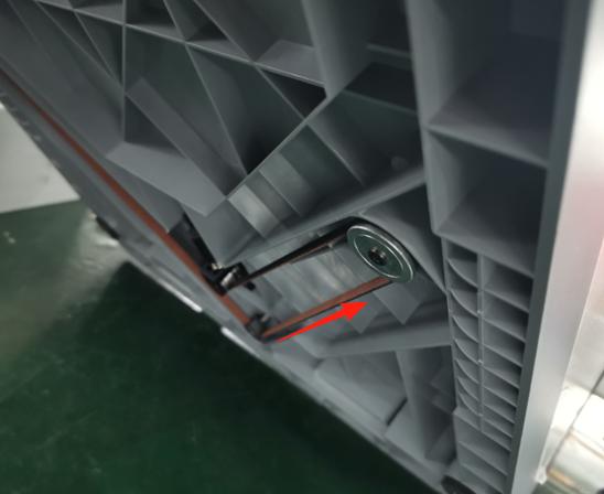
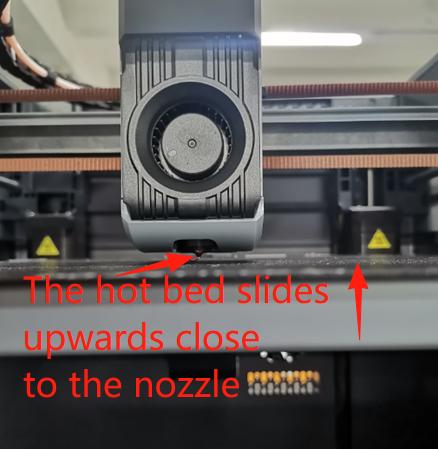
① . Place the PEI on the front of the hot bed and tilt the machine back to operate the Z-axis timing belt. Squeeze the timing belt with your hand (in the direction of the arrow) and slide the hot bed upwards towards the tip of the nozzle.
As shown in the picture:
 |
 |
② . At the bottom of the hot bed assembly, guide the hot bed wiring harness into the electrical box cable management slot.
As shown:
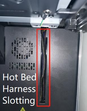
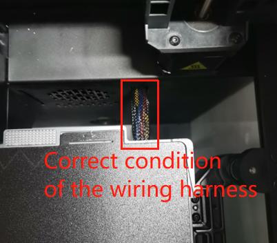
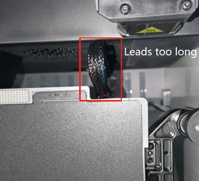
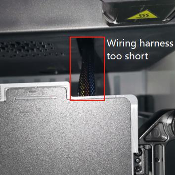
③ . Above the hot bed assembly, sink the hot bed wiring harness flat into the electrical box cable routing slot at an angle of 80 degrees in an arc - optimal. As shown in the diagram to the left:(Note: If the reserved harness is too long, the harness will bulge and scratch the nozzle. (If the reserved harness is too short, the harness will pull down tightly and cause the heat bed to zero, making it difficult for the heat bed to rise, not detecting the Z-zero point, and reporting an error.)
 |
 |
 |
¶ Step 9 - Installing the Hot Bed Wiring Harness (Electrical Box End)
① . Keep the hot bed harness vertical, put the crimp plate over the hot bed harness and lock the crimp plate screws with an H2.5 Allen key.
As shown:
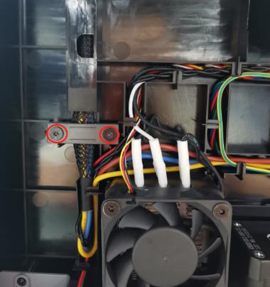
② . Guide the heat bed wiring harness (power, ground, and NTC signal wires) into the wire management slot.
As shown in the diagram:

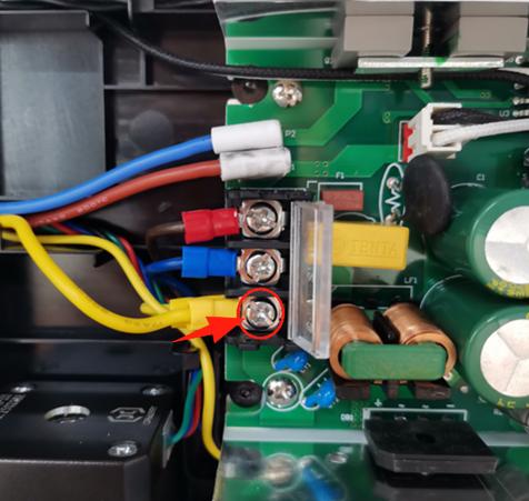
③ . Connect the earth wire to the ground terminal of the power supply, and use a PH2 Phillips screwdriver to lock the compression screw.
As shown in the picture:
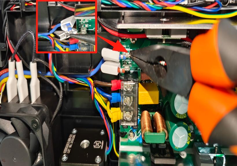
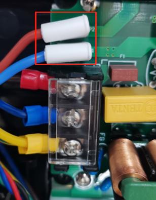
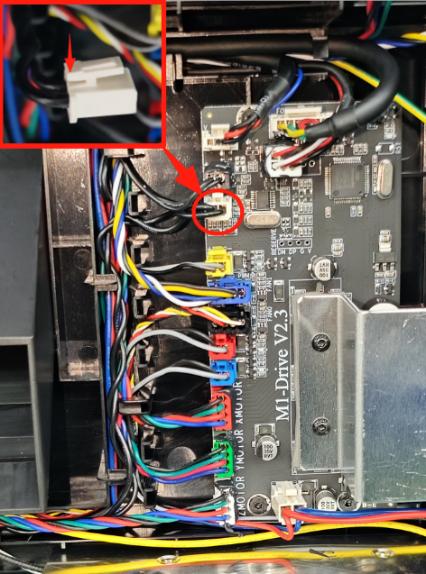
④ . Insert the power cord clamp post hot bed power cord terminal into the power insert with sharp-nosed pliers and put on the white protective rubber sleeve; pinch the NTC signal terminal bayonet facing upwards to insert the NTC signal cable into the main board.
 |
 |
 |
¶ Step 10 - Install the rear cover sheet
Installation of the back cover note: avoid Teflon PTFE tube.
Fit the rear cover sheet metal from the top left corner first, aligning the boat switch holes to fit. Lock the 8 machine tooth screws and 2 self-tapping screws in the rear cover with an H2.0 Allen key.
As shown in the picture:
 |
 |
 |
¶ Step 11 - Verification Complete
Connect the power cord and power on the machine.
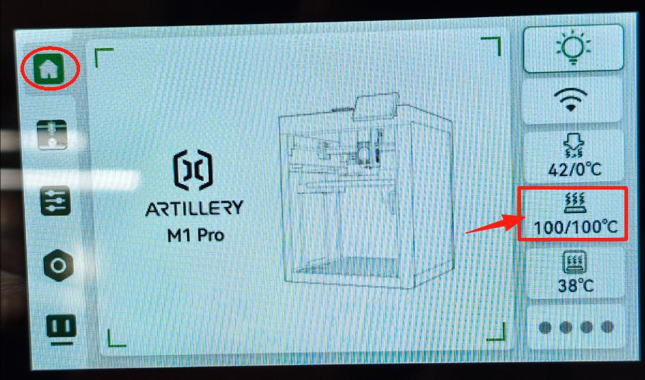
① . Enter the main interface of the screen, enter the temperature in the hot bed control field, check the hot bed warming status.
As shown in the figure:
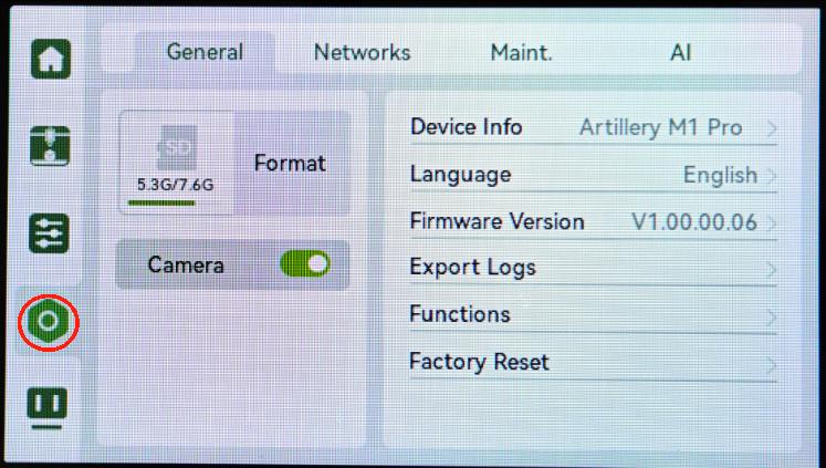
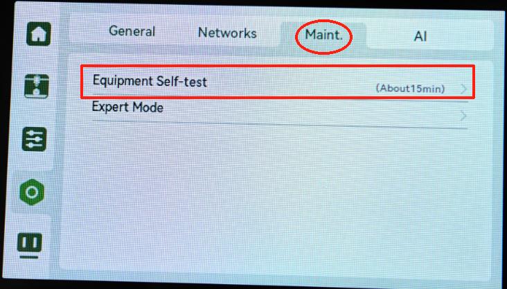
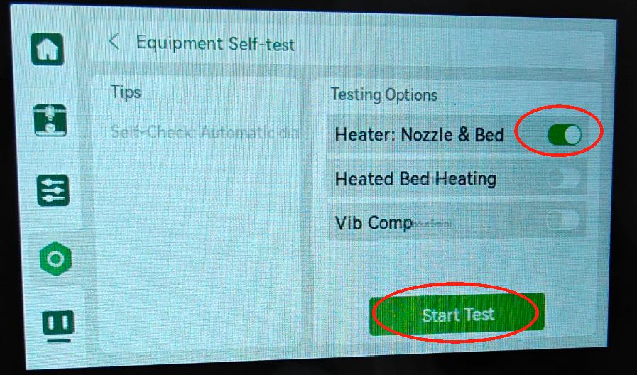
② . Ensure that the machine chamber and hot bed are free of any printing items and tooling materials. Then go to Setup→Maintenance→Equipment self-test in the menu bar on the operation screen, turn on the printhead and hot bed heating options, and click to start self-test.
As shown in the figure:
 |
 |
 |
Replacement was successful and no temperature errors or warnings occurred during calibration. Otherwise, check the connection harness and retry the check. If the problem persists, contact the service team for further assistance.