 |
 |
|
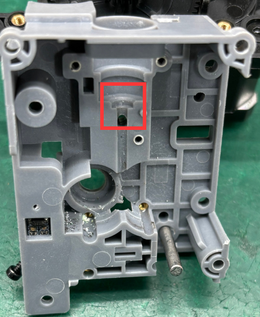
Extruder feed inlet (Before Optimization) |
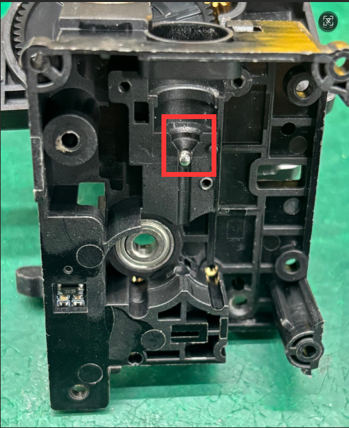
Extruder feed inlet (After Optimization) |
 |
 |
 |
¶ Required Tools and Materials
Tools:
- 1. H1.5, H2.0 Hex (Allen) Screwdrivers
- 2. PH0*2.0 Phillips Screwdriver
- 3.Tweezers
- 4.PTFE Removal Tool
Materials:
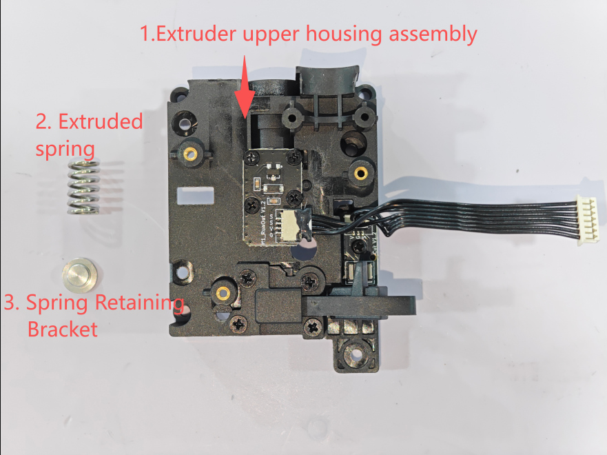
- 1.Extruder Upper Housing Assembly
- 2.Extruder Spring
- 3.Spring Retaining Bracket
 |
 |
***Warm Tips (Reminder) ***
Operational Precautions
1. Power-off Operation: You must completely disconnect the power supply before plugging or unplugging terminals. Operating with power on may cause the tool head board to burn out and result in damage to the lower machine motherboard.
2. Special Tool Specification: Use tweezers for operations. Pry open and pull out gently during operation; brute force is prohibited. Violent operation will lead to:
- Terminal wire damage
- Socket detachment/damage
- Poor contact causing short circuits
¶ Guide to Disassembling the Tool Head Extruder
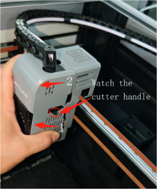
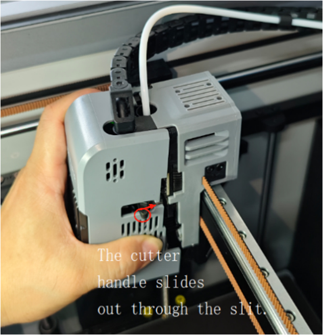
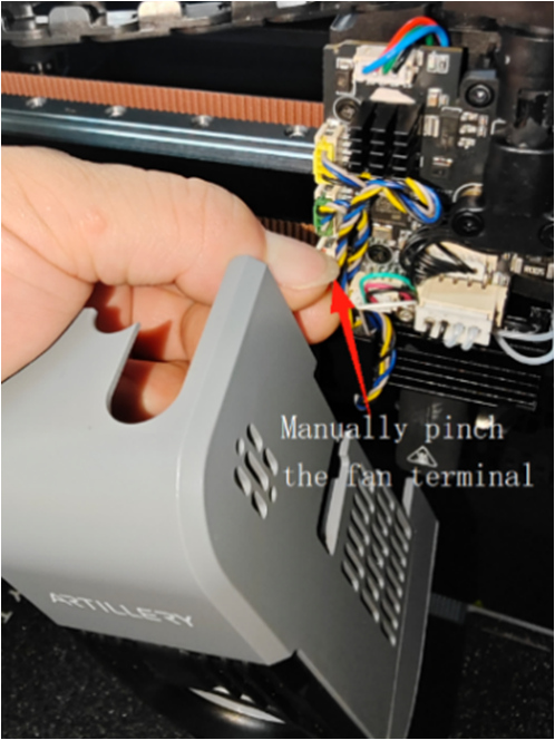
1. Remove the Tool Head Cover
Process for removing the nozzle cover: Manual — First detach the lower part of the cover, then lift upwards to remove the cover. Note: The cutter handle must slide out through the notch in the cover. After removing the cover, please pinch the model fan terminal and pull it out. Operation as shown in the figure:
 |
 |
 |
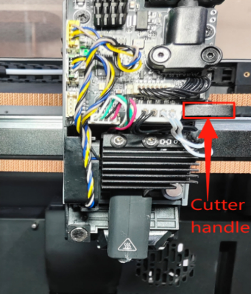
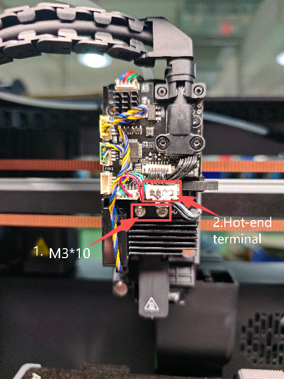
2. Remove the Hot End Assembly
Press the cutter handle to cut off any residual filament inside the extruder. As shown in Figure A: Use an H2.0 Hex wrench to remove the two M3*10 button head screws holding the hot end assembly, and unplug the hot end assembly terminal. As shown in Figure B
|

|
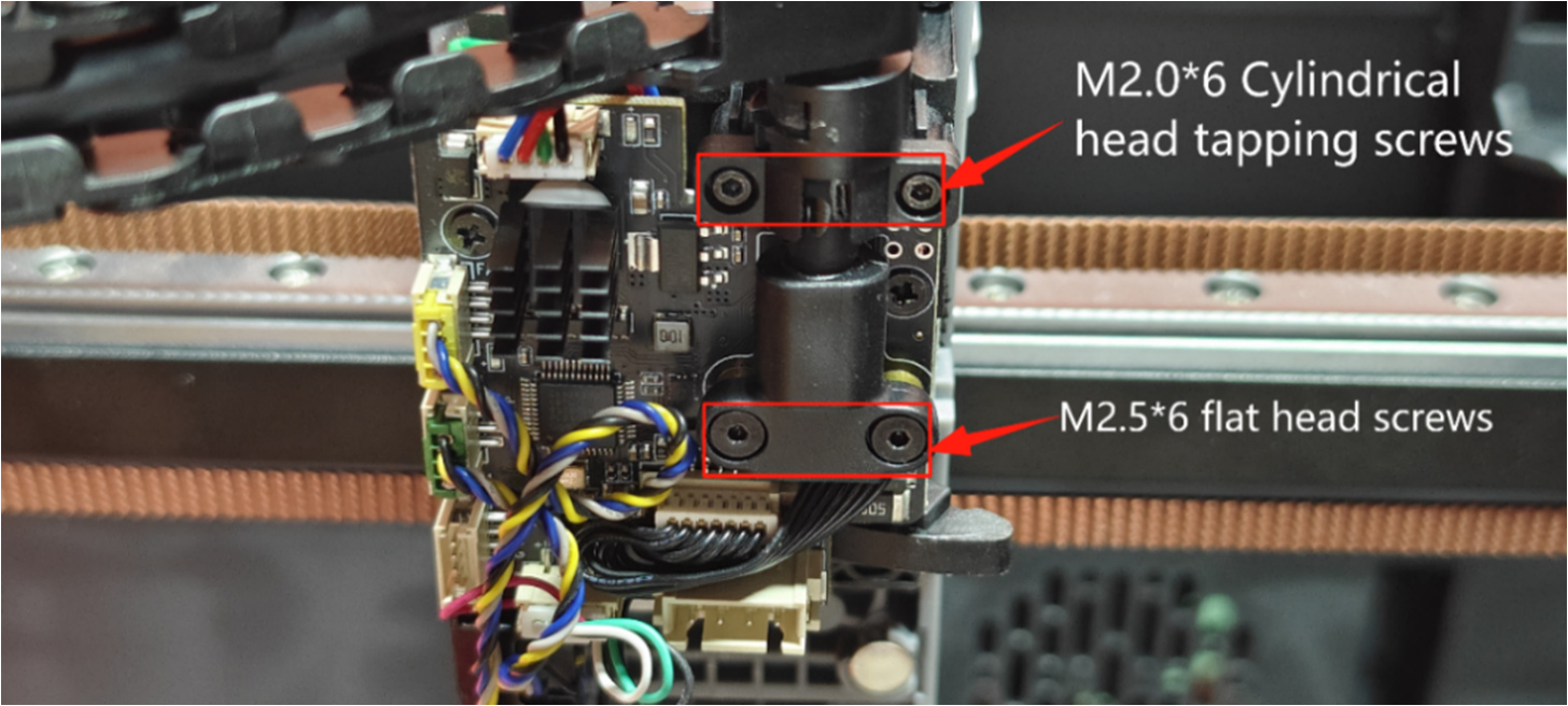
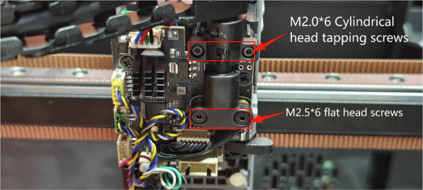
3. Disassemble Nozzle Cable Connector
- Use an H1.5 Hex screwdriver to remove the cable connector screws (2 pcs M2.06 cylindrical head self-tapping screws, 2 pcs M2.56 flat head screws) and remove the cable connector.
 |
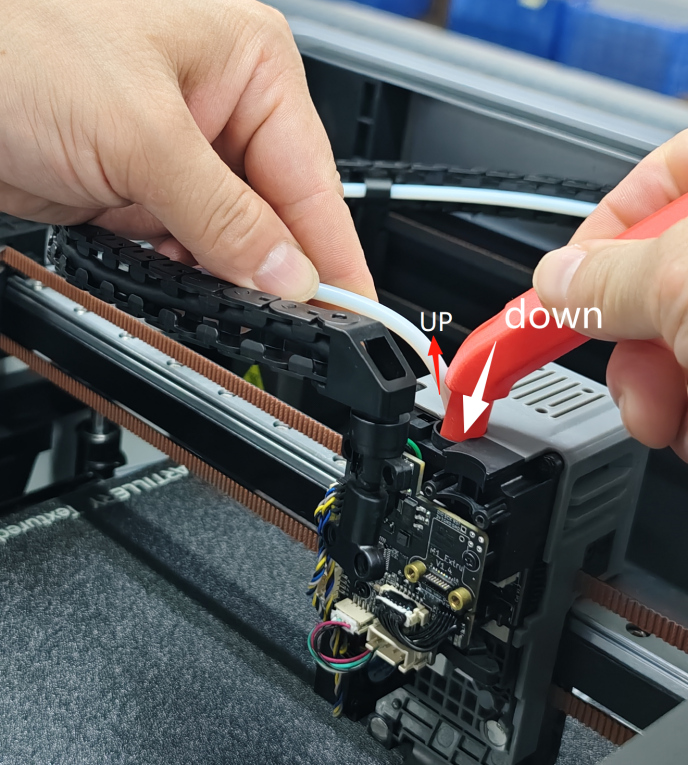
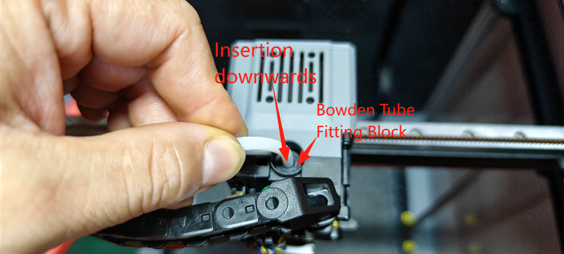
- Use the PTFE removal tool on the right side to press down on the extruder Bowden tube fitting block (material pipe end), and manually pull out the white material tube with your left hand.
 |
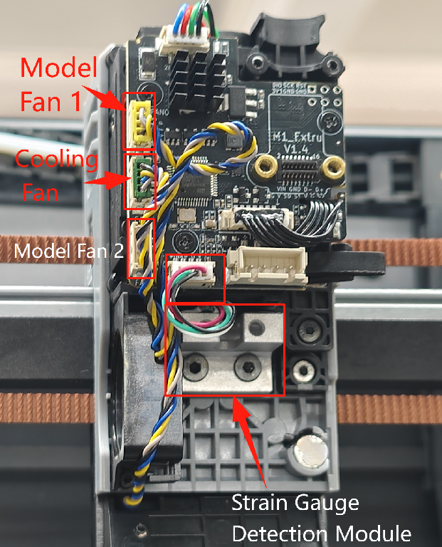
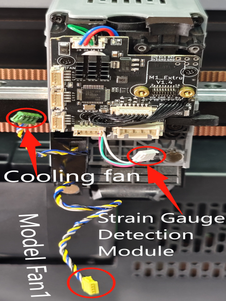
4. Remove Fans & Leveling Sensor Terminals on Extruder Small Board
Remove the hot end cooling fan, rear model fan 1, and the strain gauge detection module (leveling sensor) terminals.
 |
 |
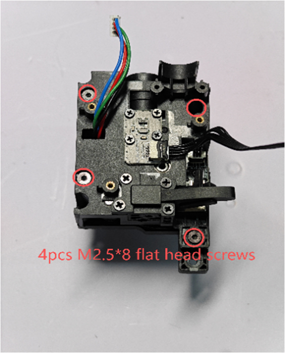
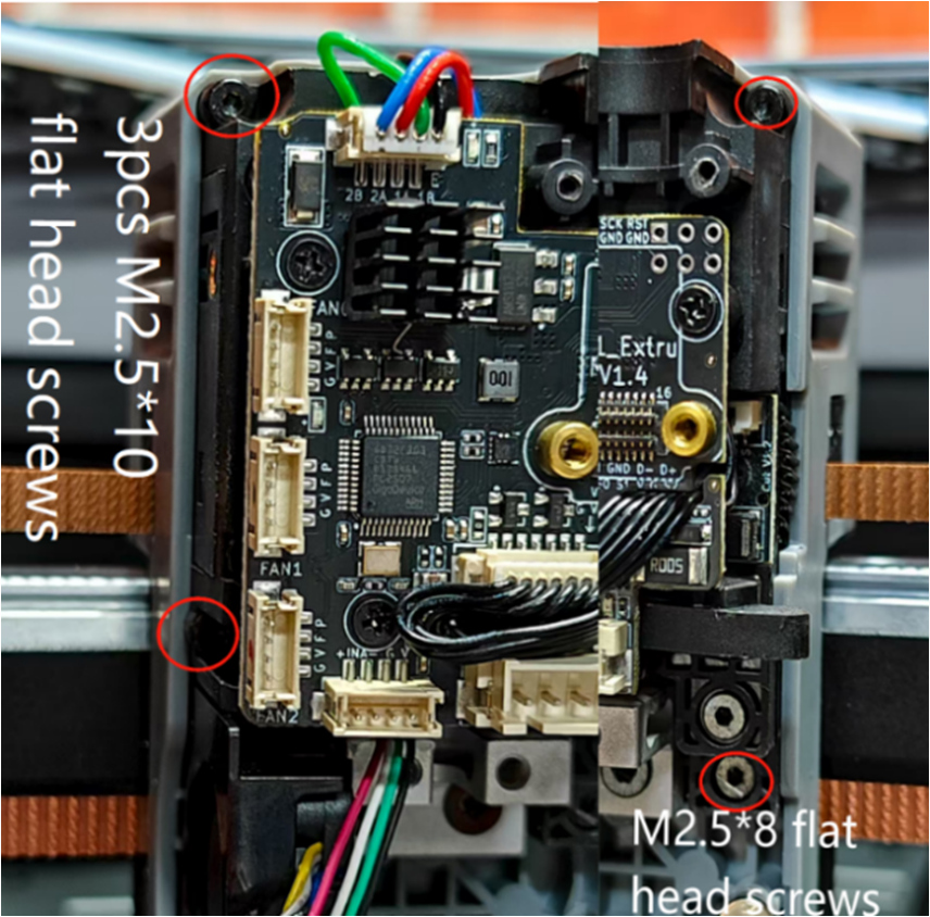
5. Remove the Extruder
Use an H1.5 Hex wrench to remove the 4 fixing screws on the extruder (3 pcs M2.510 flat head screws, 1 pc M2.58 flat head screw). Take out the extruder component. As shown in the figure.
 |
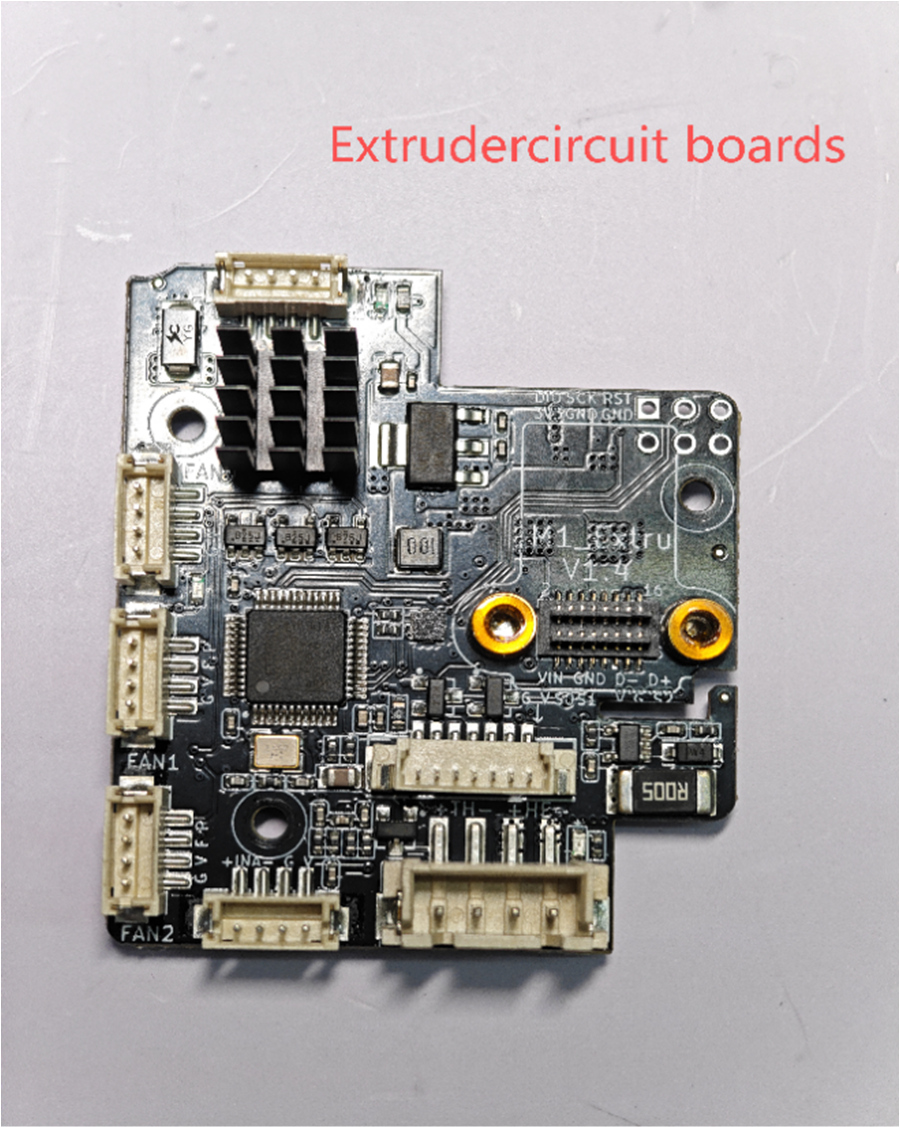
6.Disassemble Extruder Circuit Board
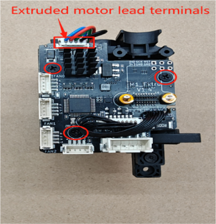
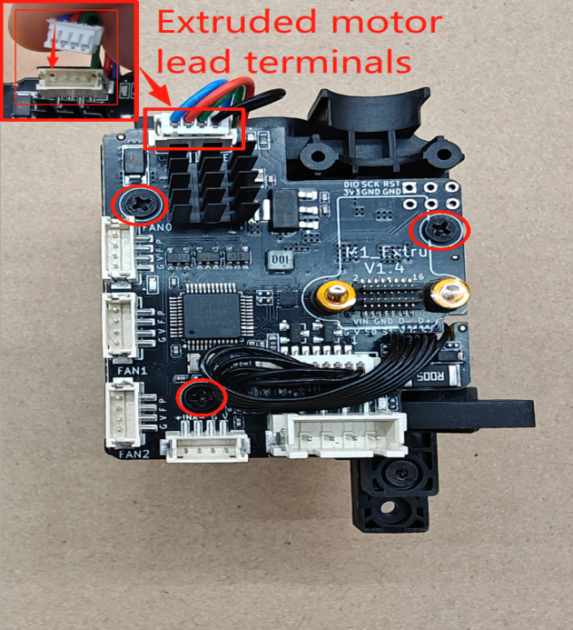
① Use a PH1 Phillips screwdriver to remove the 3 M2.0*5 flat head Phillips fixing screws on the circuit board. Manually unplug the extruder motor terminal.
 |
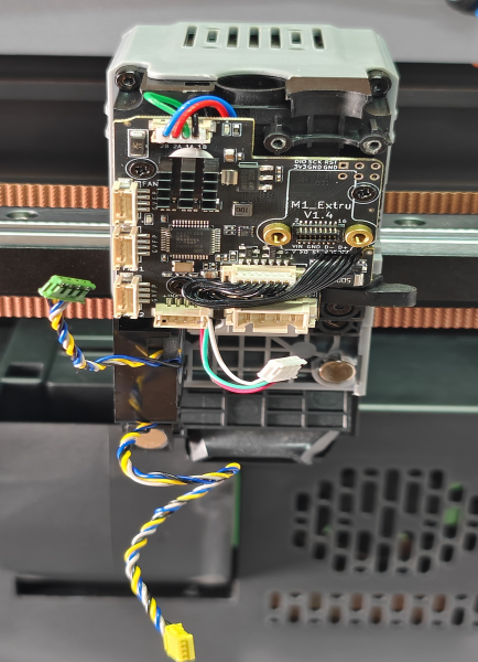
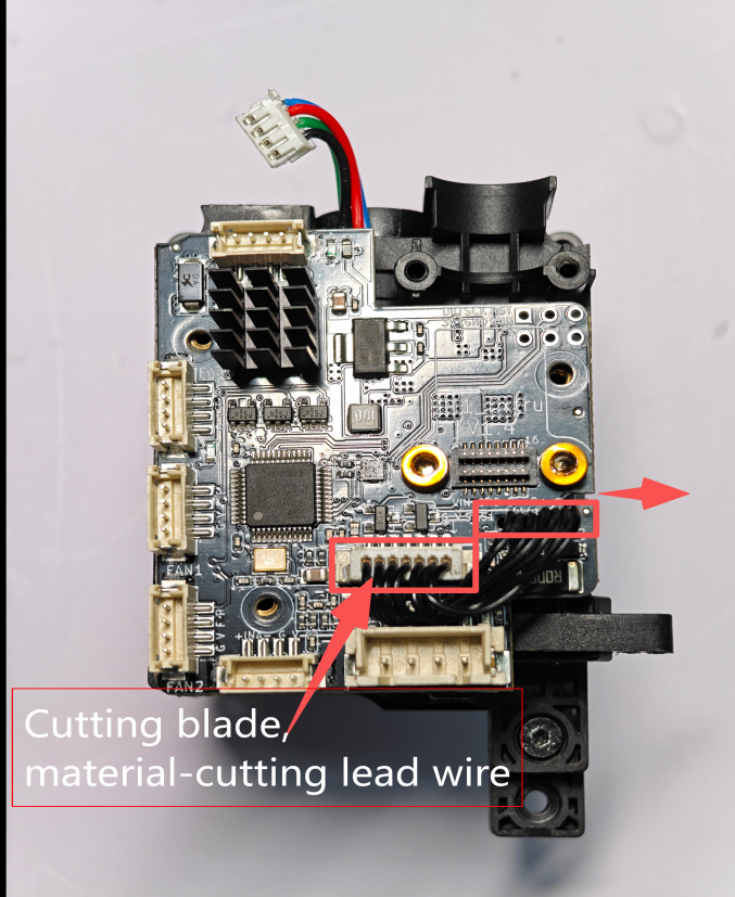
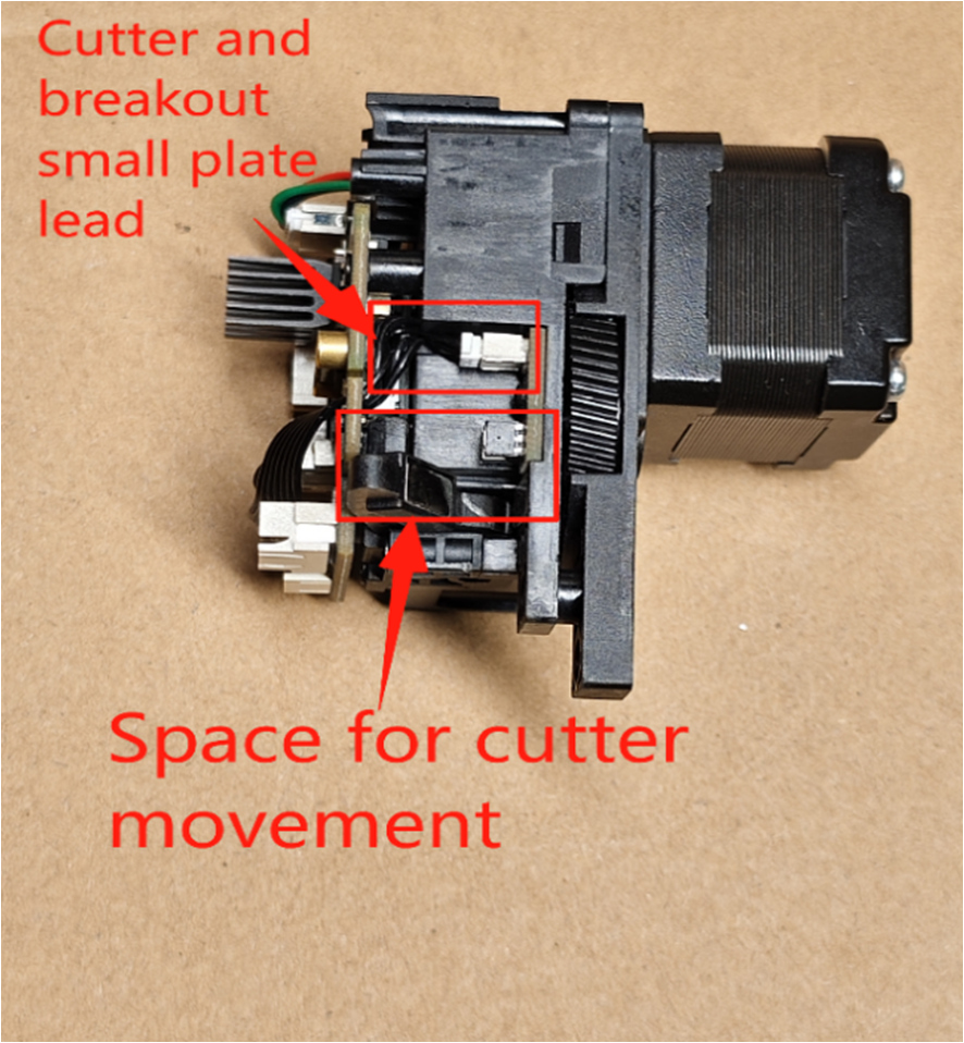
② Unplug the filament detection and cutter detection small board wire terminals from the extruder circuit board, and slide the wires out from the right side of the circuit board.
 |
 |
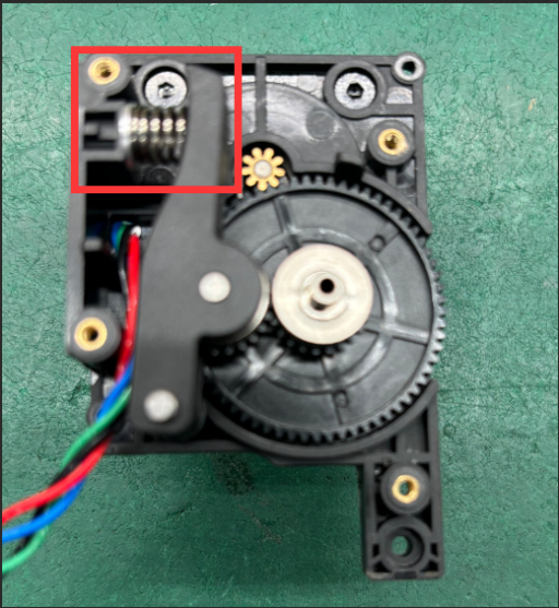
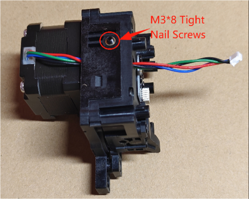
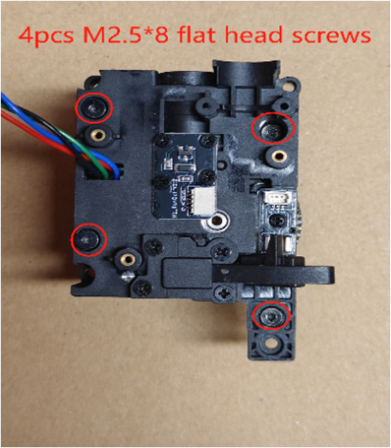
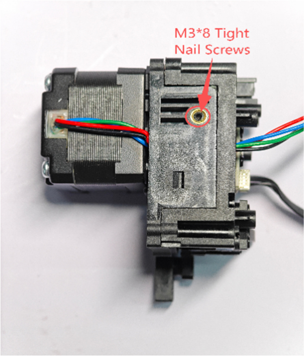
7.Disassemble Extruder Upper Shell
① Use an H1.5 Hex screwdriver to loosen the side set screw (tight nail screw), then remove the 4 M2.5*8 flat head screws on the extruder upper shell.
 |
 |
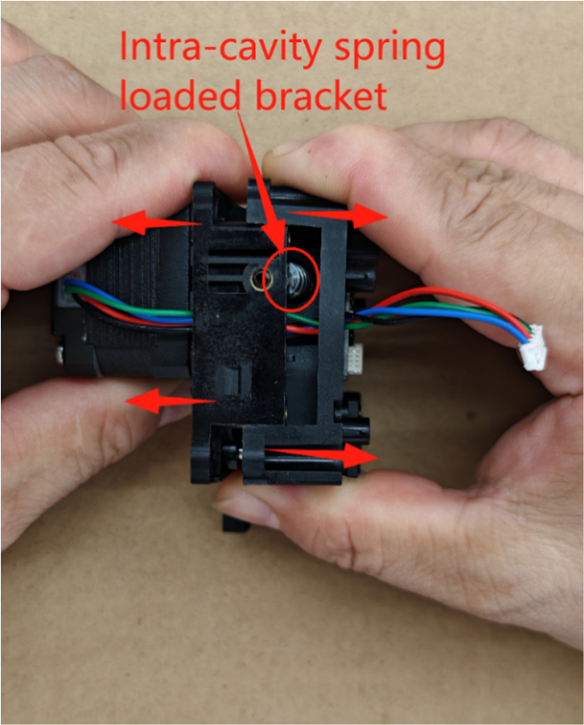
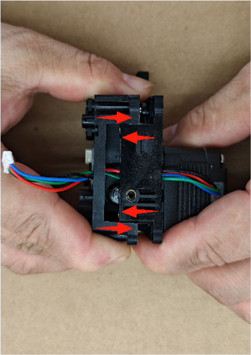
② Separate the extruder upper and lower shells by pulling them in opposite directions as shown by the arrows.
 |
¶ Replace & Install Extruder Accessories
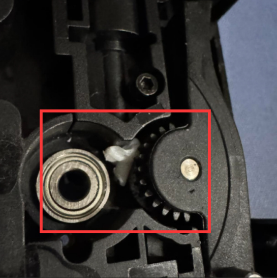
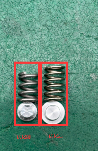
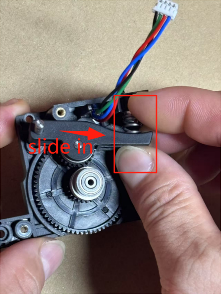
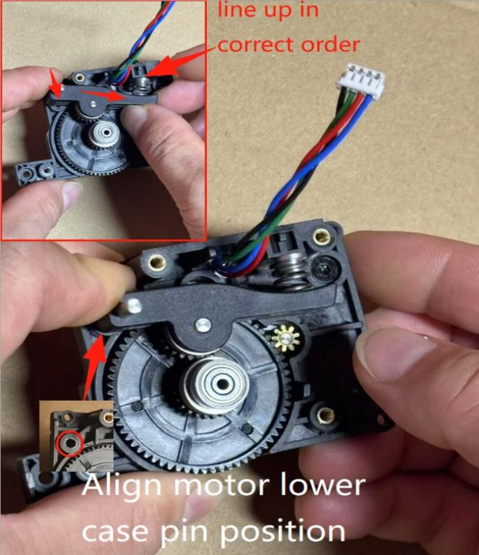
1. Replace with the new spring & spring retaining base.
2. Pinch the (handle component & compression spring, spring bracket end) with your right hand and snap them into place, aligning the large gear shaft with the small gear. Pinch the handle pin end with your left fingers, aligning it with the pin position on the motor lower shell. Press the spring bracket with your right fingers to align with the set screw position, release, and press the handle pin into the lower shell to lock and fix it. As shown in the figure.
 |
 |
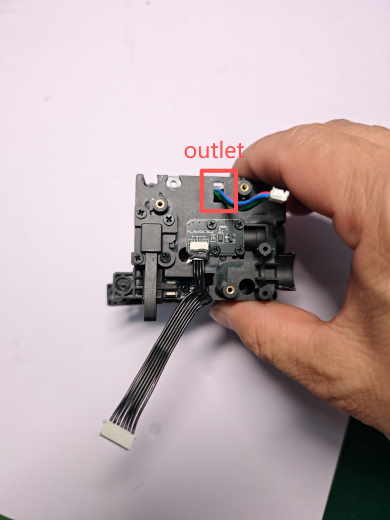
3. Install New Extruder Upper Shell
Thread the lower shell motor lead wire through the upper shell motor outlet, align the upper and lower shells, and press them together tightly. Use an H1.5 Hex wrench to lock the fixing screws (4 pcs M2.0*8 flat head self-tapping screws) and screw the left side set screw flush with the extruder surface shell. As shown in the figure.
 |
 |
 |
 |
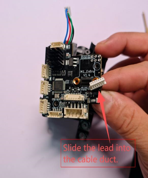
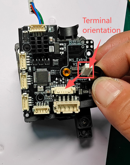
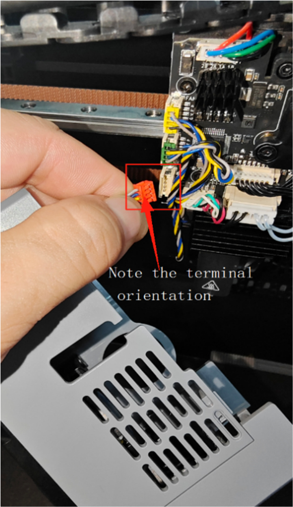
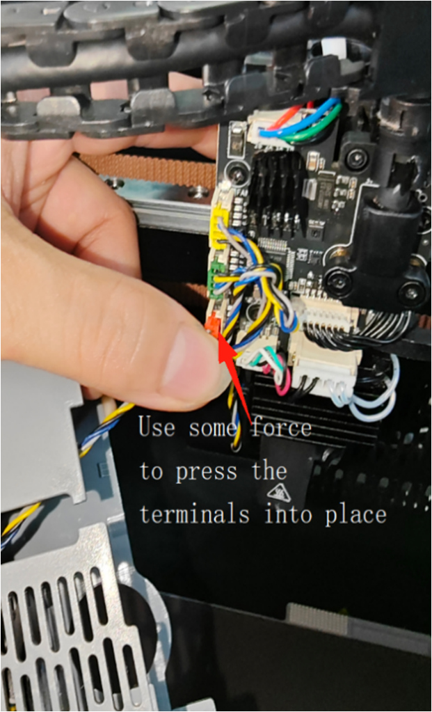
4. Install Extruder Circuit Board
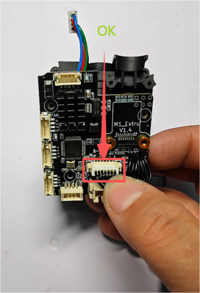
① Align the extruder upper shell (cutter and filament runout) wires and slide them into the cable slot. Figure A. Orient the wire terminals correctly and install them onto the extruder circuit board, inserting the wire terminals into the cutter & filament runout sockets on the board. Figure B.
 |
 |
 |
|
A Imagem |
B Imagem |
|
② Install the extruder motor wire terminal into the motor socket on the extruder circuit board. Use a PH1 Phillips screwdriver to lock the 4 M2.5*5 Phillips flat head screws fixing the extruder circuit board. Flip the extruder component to the left to check that the cutter and filament runout wires must avoid the cutter handle position to prevent cutter malfunction.
 |
 |
5. Install Tool Head into Extruder Component
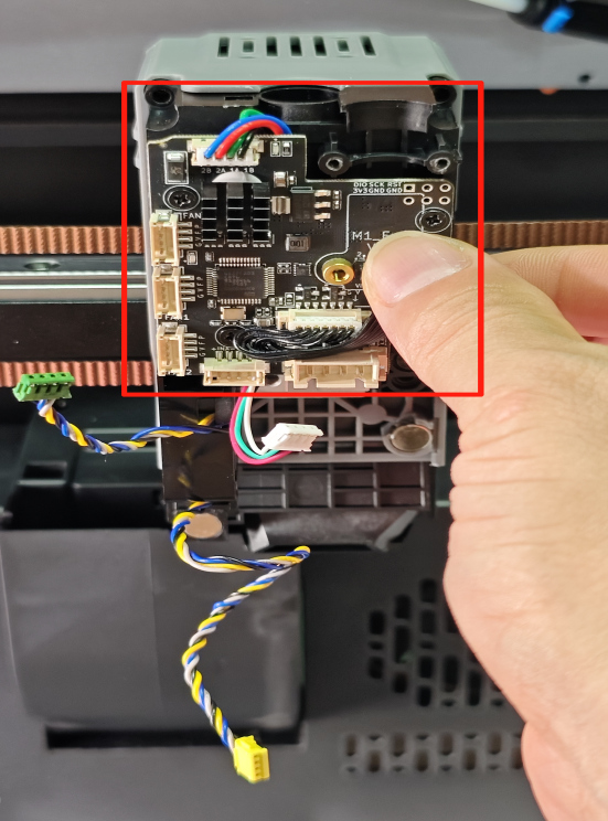
①.Place the extruder component into the nozzle middle frame of the machine. Use an H1.5 Hex wrench to lock the 3 M2.510 flat head screws and 1 M2.58 flat head screw.
 |
 |
②.Plug the hot end cooling fan, rear blower fan, and strain gauge detection module terminals into the corresponding sockets on the extruder circuit board.
 |
|
6. Install Extruder Cable and PTFE Tube
①Install the cable female socket onto the male socket on the extruder board, aligning it with the screw pillars. Use an H1.5 Hex screwdriver to lock the cable connector screws (2 pcs M2.56 flat head screws, 2 pcs M2.56 cylindrical head self-tapping screws).
 |
②.Insert the white material tube (PTFE tube) into the extruder Bowden tube fitting block
 |
7. Install Hot End Assembly
Use an H2.0 Hex wrench to lock the 2 M3*10 button head screws of the hot end assembly, and install the hot end assembly terminal into the socket on the extruder circuit board. As shown.
 |
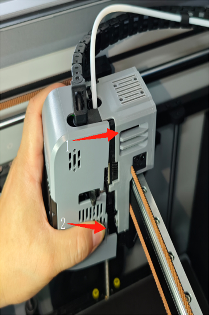
8. Install Tool Head Cover
First, insert the nozzle cover cooling fan terminal into the corresponding socket on the extruder small board (pay attention to terminal direction). Position the cooling fan wire towards the extruder small board. When installing the nozzle cover, install from the top end onto the upper end of the extruder first, then fit the lower part. During installation, ensure the cutter handle slides into the nozzle cover through the notch; the cover will be sucked into place smoothly with the help of the magnet. As shown.
 |
 |
 |
Note: The removed filament runout small board, cutter small board, and cutter component accessories can be kept for future repair use.
Optimization steps above: If you have questions or need help, please send an email to contact us at support@artillery3d.com for after-sales service.