Operating Precautions 1. Power off operation, the power must be completely disconnected before plugging and unplugging the terminals. Power-on operation may cause the power supply to burn out and cause chain damage to the motherboard.
2. Special tool specification, use tweezers to operate. When operating, you need to gently pry open and pull out, and it is forbidden to use brute force to pull. Violent operation will lead to:
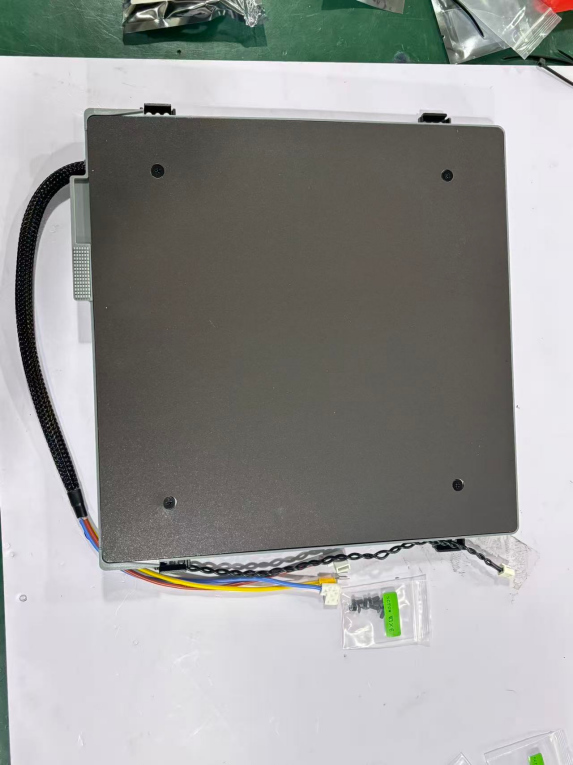
Turn on the printer and control the heat bed to move downward through the display screen to place the heat bed at the bottom, exposing the heat bed harness outlet on the front of the electrical box. Then turn off the printer and unplug the power cord to remove the glass cover.
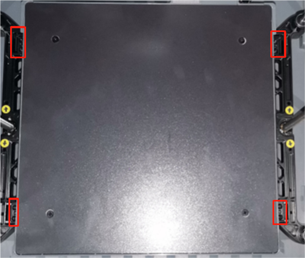
Note: This process involves two types of screws, please distinguish them and place them in different areas to avoid confusion.
As shown in the figure: Remove the 2 self-tapping screws and 8 machine screws on the rear cover plate in order. Remove the rear cover.
¶Step 4 - Remove the heated bed harness (electrical box end)
1. Use a H2.5 Allen wrench to remove 2 self-tapping screws and remove the wire clamp.
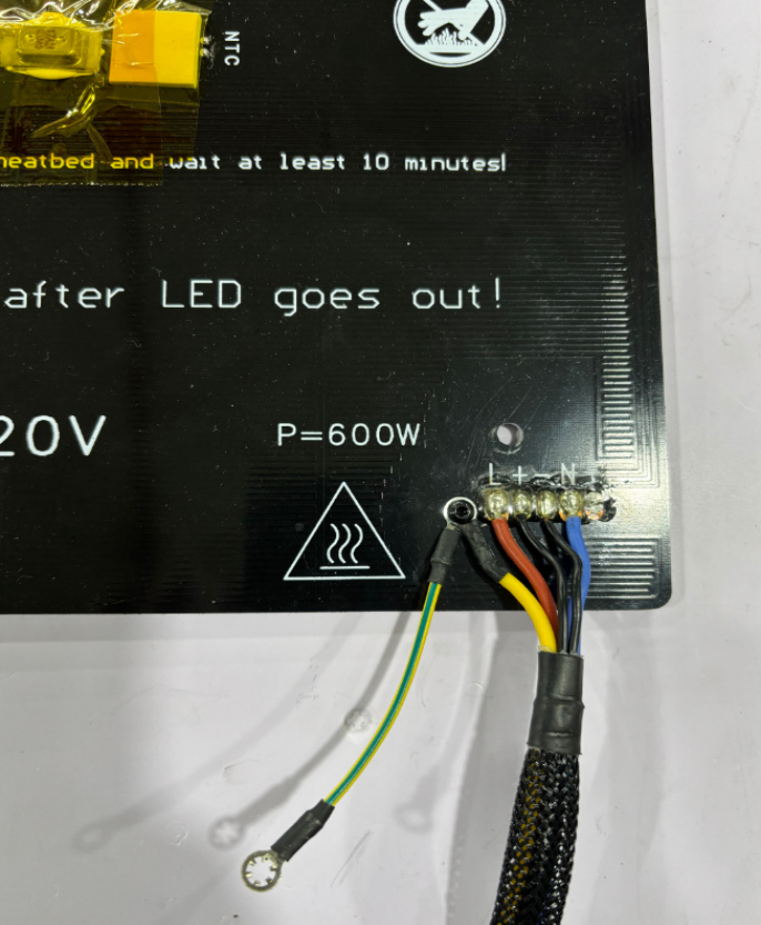
2. Use a PH2 Phillips screwdriver to loosen the power ground wire clamping screw and remove the heated bed ground wire terminal.
3.Loosen theheated bed power cord terminalwhite protective sleeve, use needle-nose pliers to hold the upper end of the terminal and pull it out, pull out the two power cords.
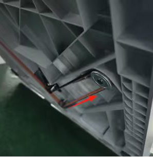
4. Pinch the buckle of the heated bed NTC signal wire terminal in the direction of the arrow shown in the figure and pull out the terminal.
Pinch the buckle of the heated bed NTC signal wire terminal in the direction of the arrow shown in the figure and pull out the terminal.
Remove the heated bed wire from the wiring trough of the electrical box.
Use a H2.0 Allen wrench to remove 8 M3*6 pan head screws that secure the heated bed bracket, move the heated bed assembly and heated bed wiring harness out at an angle, and remove the heated bed assembly from the front of the door.
Tilt the heated bed assembly from the front and side into the machine cavity, install it on both sides of the Z slider, place it in the center, and insert the harness into the electrical box heated bed wire outlet. Use a H2.0 Allen wrench to lock in 8 M3*6 round head screws to secure the heated bed bracket and tighten.
Figure a
Figure a
Figure b
Figure b
¶ Step 7 - Adjust the position of the heated bed component harness
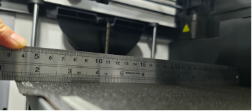
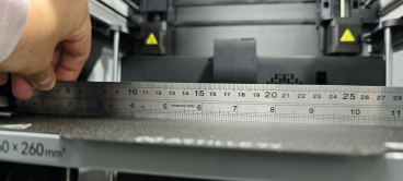
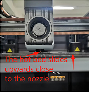
1.Place the PEI on the front of the heated bed, and tilt the machine backwards to operate the Z-axis synchronous belt. Pinch the synchronous belt with your hand (slide in the direction of the arrow) to allow the heated bed to slide upward and close to the tip of the nozzle. As shown in the figure:
2. At the bottom of the heated bed assembly, guide the heated bed harness into the wiring trough of the electrical box. As shown in the figure:
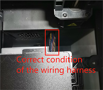
3. Above the heated bed assembly, sink the heated bed harness straight into the wiring trough of the electrical box at an 80-degree arc shape - the best condition. As shown in the left figure: (Note: If the reserved harness is too long, the harness will bulge and scratch the nozzle. If the reserved harness is too short, the harness will pull down tightly, causing the heated bed to have difficulty returning to zero and rising, and the Z-zero point cannot be detected, resulting in an error.)
¶ Step 8 - Install the heated bed harness (electrical box end)
1. Keep the heated bed harness vertical, cover the wiring harness with the pressure plate, and use a H2.5 Allen wrench to tighten the pressure plate screws. As shown in the figure:
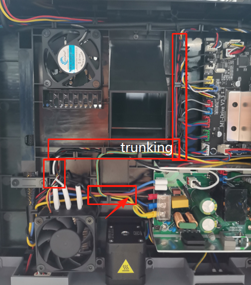
2. Route the heated bed wiring harness (power line, ground line, NTC signal line)into the wire management channel. As shown in the figure:
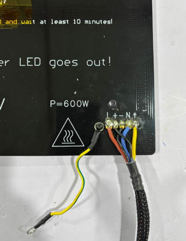
3. Connect the ground wire to the power supply grounding terminal and tighten the pressure screw with a PH2 Phillips screwdriver, as shown in the figure.
4. Use needle-nose pliers to insert the hot bed power cord terminal of the power cord clamp post into the power supply chip, and put on a white protective sleeve; hold the NTC signal terminal bayonet with your hand facing up and insert the NTC signal wire into the motherboard.
Installation of the rear cover: Avoid the Teflon PTFE tube.
First install the rear cover plate from above, align with the rocker switch hole and install it. Use a H2.0 Allen wrench to tighten the 8 machine screws and 2 self-tapping screws on the rear cover, as shown in the figure.
1· Enter the main screen interface, enter the temperature in the hot bed control bar, and check the hot bed heating status, as shown in the figure.
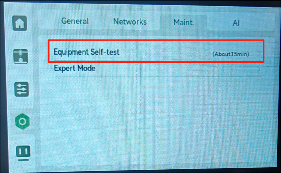
2. Make sure there are no printing items, tools, or materials in the machine chamber and on the hot bed. Then go to Settings → Maintenance → Device Self-Check in the menu bar on the operation screen, turn on the nozzle, hot bed heating option, and click to enter the start self-check, as shown in the figure.
¶Step 11 After the replacement is successful, enter the hot bed leveling guide.
1: Nozzle & Hot Bed Platform Calibration Center Reference Point:
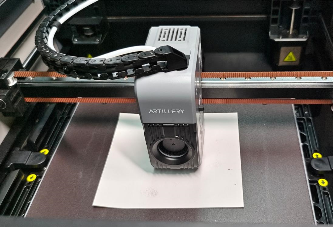
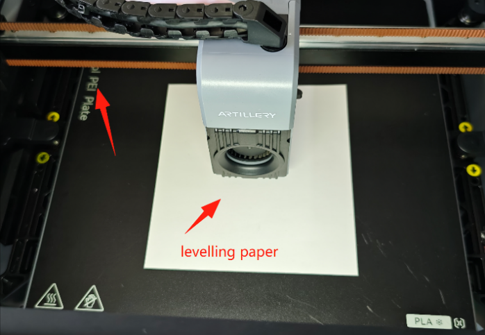
1. Manual - Remove the PEI from the hot bed plate, move the extruder head to the center of the hot bed platform (middle of the X & Y axes);
And place a leveling paper / ordinary A4 paper on the hot bed plate, directly below the nozzle. As shown in the figure:
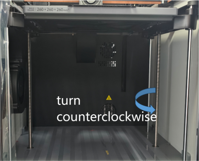
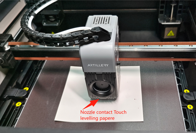
2. Adjust the gap between the nozzle and the reference point (center point): Manually - Tilt and pull down the machine's Z-axis belt to raise the hot bed. Fine-tune the Z-axis lead screw (in the direction of the arrow) until the nozzle just touches the leveling paper. As shown in the figure: Note: Only the center point leveling position needs to rotate the Z-axis lead screw, other leveling points adjust the hot bed with a PH2 Phillips screwdriver.
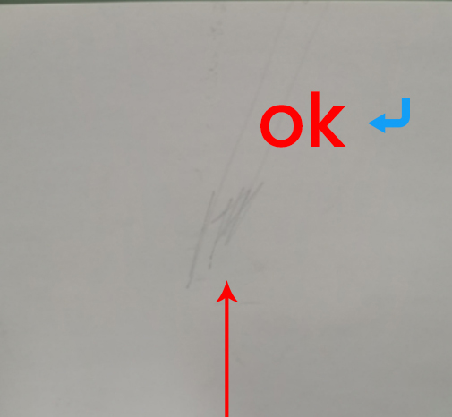
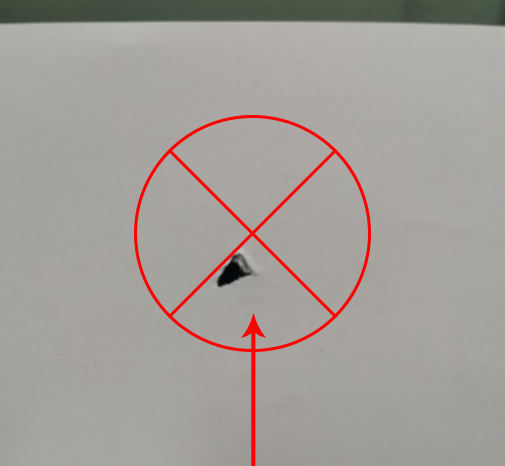
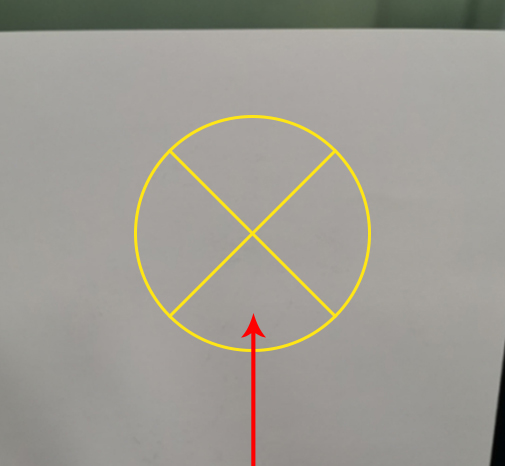
Calibration leveling paper is correct as follows: Manually try to pull the leveling paper back and forth. Best state: The leveling paper can move normally, and you can feel the slight resistance of the nozzle scraping the leveling paper ("slightly scraping the nozzle"), and leave a slight scratch on the paper as shown in the figure below.
Too tight: Paper jam (causing the print to scrape the PEI plate / clog / wrap). Too loose: No resistance and no scratches (causing the print to not stick to the PEI / fried noodles / wrap).
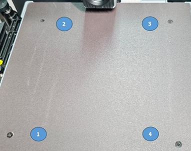
Manual - Slowly move the nozzle and leveling paper to the first leveling point simultaneously, so that the nozzle accurately moves above the first leveling point, leaving enough space directly above the hot bed leveling screw to insert a screwdriver. Note: During the process of adjusting each leveling point, you need to hold the bottom of the hot bed leveling point with your palm to prevent the hot bed from sliding down, which may cause the hot bed surface to be uneven. (During the process of moving the nozzle, you need to observe the distance between the hot bed and the nozzle in real time, and adjust the rotation direction of the adjustable screw to ensure that there is a gap between the hot bed and the nozzle that can fit a leveling paper) As shown in the figure:
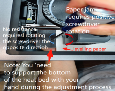
Calibration process: If you feel too much resistance when moving the leveling paper (the leveling paper cannot even slide under the nozzle), or even the nozzle obviously scratches the hot bed plate (dangerous!), it means that the gap is too small and too tight, causing the nozzle to jam the paper.
If the leveling paper slides out easily without any resistance, it means that the gap is too large and too loose with no scratches. You need to adjust the adjustable cross screw:
¶ The gap is too small (the nozzle is too low and jams the paper) - adjust the adjustable cross screw clockwise. The gap is too large, the leveling paper has no resistance and no scratches (the nozzle is too high) - adjust the adjustable cross screw counterclockwise. Rotate the adjustable cross screw while checking the resistance of the leveling paper to adjust the leveling paper in the nozzle & hot bed leveling process to the best state (the leveling paper has slight scratches).
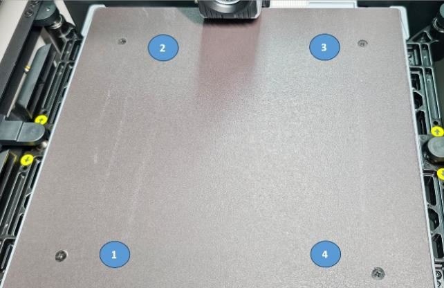
3: Repeat calibration other leveling points
Refer to the leveling point sequence shown in the figure and move to directly above each leveling point in turn. Repeat step 2 for each point to level, and adjust all the points that need to be leveled to the best state.
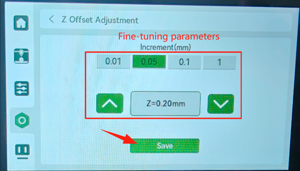
¶4. After the calibration is complete, put the PEI back on the hot bed, power on and turn on the machine operation. The screen enters the adjustment Z=0 offset (center reference point). Put in the leveling paper and fine-tune it. Adjust the Z offset to the best state (the leveling paper has slight scratches) and save and return to exit. as the picture shows:
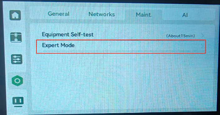
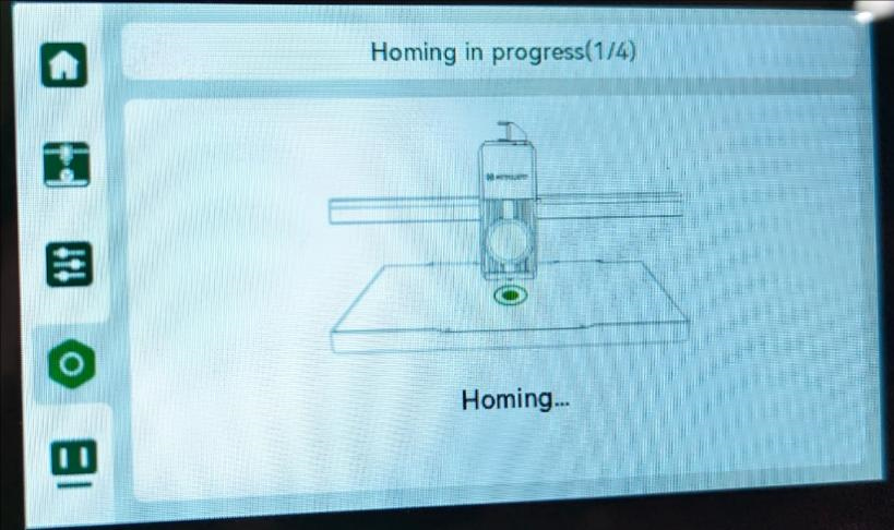
¶ 5. Enter device self-test - nozzle/hot bed heating, hot bed automatic leveling, vibration compensation detection. After waiting for completion, you can print normally. as the picture shows:
Replacement successful, and no temperature errors or warnings occurred during the calibration process. Otherwise, check the wiring harness and try again. Check. If the above steps are ineffective, please send an email to contact us support@artillery3d.com after-sales service.
-en_belindoc-2.jpg)
-en_belindoc-3.jpg)
-en_belindoc-4.jpg)
-en_belindoc-5.jpg)
-en_belindoc-6.jpg)
-en_belindoc-7.png)
-en_belindoc-9.jpg)
-en_belindoc-10.jpg)
-en_belindoc-11.jpg)
-en_belindoc-12.jpg)
-en_belindoc-13.jpg)
-en_belindoc-14.jpg)
-en_belindoc-15.jpg)
-en_belindoc-21.jpg)
-en_belindoc-23.jpg)
-en_belindoc-20.jpg)
-en_belindoc-24.jpg)
-en_belindoc-25.png)
-en_belindoc-27.jpg)
-en_belindoc-28.jpg)
-en_belindoc-29.jpg)
-en_belindoc-30.jpg)
-en_belindoc-31.jpg)
-en_belindoc-32.jpg)
-en_belindoc-33.png)
-en_belindoc-34.png)
-en_belindoc-38.jpg)