¶ What is a synchronous belt
A synchronous belt is a flexible, toothed, ring-shaped belt primarily used for transmitting rotational force and reciprocating linear motion, characterised by high precision and no slippage. Synchronous belts are made with steel cables or glass fibre as the reinforcement layer, covered with polyurethane or neoprene rubber. The inner circumference of the belt is designed with teeth to mesh with toothed pulleys for power transmission. During operation, there is no relative slippage between the belt and the synchronous pulley, ensuring precise and constant transmission ratios.
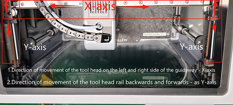
The XY synchronous belts used on the M1pro 3D printer have the following specifications: X: 1533mm, Y: 1539mm, with a 6mm-wide open belt. One long and one short belt are used, with the X-axis 1533mm synchronous belt installed above the tool head and the Y-axis 1539mm synchronous belt installed below the tool head. These belts connect the XY stepper motors to the tool head and drive its movement in the XY directions.
.png) |
.jpeg) |
When to replace
- The synchronous belt has aged or worn out, affecting the printing function.
- Synchronous belt breakage (refer to the synchronous belt breakage replacement tutorial)
¶ Tools and materials required
- New XY synchronous belt
- H1.5 & H2.5 Hexagon Socket Wrench
- tweezers
- quick-drying glue
- masking tape
- Model tooling
¶ ⚠️Safety warnings and machine status before starting operation
⚡️When performing disassembly work, make sure that the printer is disconnected from the power supply.
¶ Important notes
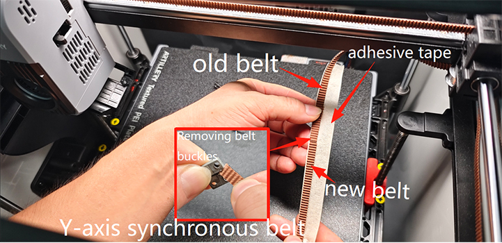
- Before replacing the synchronous belt, do not pull out the old belt directly. It can be used to pull the new belt into place during installation.
- The tooth directions of the new and old belts must be consistent.
- Before replacing the synchronous belt, you should understand the entire path of the old belt.
- When pulling the new synchronous belt with the old synchronous belt, do not move too quickly. If you encounter significant resistance, stop immediately to check and confirm that there are no abnormalities in the adhesive tape where the new and old synchronous belts are bonded before continuing the pulling operation.
- The adhesive bonding between the new and old synchronous belts must be sufficiently strong to prevent breakage when the belt is running.
Special Note: This guide is intended to provide a simpler solution than normal procedures. By using the old belt for traction, the belt can be replaced without removing the left and right side panels. Please read the entire guide carefully before deciding whether to follow these instructions.
¶ Guide to replacing the synchronous belt on the tool head
¶ Lowering the height of the hot bed
¶ Step 1: Turn on the printer, use the display screen to control the Z-axis hot bed to move downwards to a position 15 cm below the tool head, then turn off the printer, disconnect the power cord, and remove the glass cover.
.png) |
¶ Step 2: As shown in the figure: Remove the internal circulation components, remove the two self-tapping screws and eight machine screws on the rear cover plate, and remove the rear cover plate.
.png) |
.png) |
.png) |
¶ Steps for replacing the X-axis synchronous belt
¶ Step 1: Loosen the X-axis synchronous belt tensioner.
Use an H1.5 hex wrench to loosen the two adjustment screws on the X-axis tensioner, push the tensioner to the far right limit position to loosen the synchronous belt, and then use an H1.5 hex wrench to tighten the tensioner adjustment screws.
.png) |
¶ Step 2: Remove the X-axis synchronous belt mounting clip.
Use an H1.5 hex wrench to remove the four M2.5*5 flat round head screws, remove the tool head left and right belt buckles ‘L’ and ‘R’; and cut the synchronous belt with scissors from the right side (R) belt buckle position.
.jpg) |
.png) |
¶ Steps for replacing the Y-axis synchronous belt
¶ Step 1: Loosen the Y-axis synchronous belt tensioner.
Use an H1.5 hex wrench to loosen the two adjustment screws on the Y-axis tensioner, push the tensioner to the far left limit position to loosen the synchronous belt, and then use an H1.5 hex wrench to tighten the two screws on the tensioner.
.png) |
¶ Step 2 :Remove the rear model fan from the tool head
Using an H2.5 hex key, remove the three M3×16 cylindrical-head self-tapping screws securing the rear model fan.
.png) |
Using an H1.5 hex key, remove the two M2.6 x 10 flat-head self-tapping screws securing the rear model fan duct assembly.
.png) |
¶ Step 3 :Remove the Y-axis synchronous belt mounting clip
Using an H1.5 hex key, remove the four self-locking screws securing the Y-axis synchronous belt clamp.
.png) |
¶ Steps for replacing adhesive tape on synchronous belts (X-axis synchronous belt length: 1533mm, Y-axis synchronous belt length: 1539mm)
Using masking tape/sturdy adhesive tape (cut to length: 13cm, width: 2cm), wrap the new and old synchronous belts tightly together along their centre line. (Note: If the synchronous belt is severed, trim the cut edge flush and wrap it with tape before proceeding.) When securing the tape, ensure both belts are oriented correctly and bonded firmly.
¶ Step 1:X-axis synchronous belt connection operation.
Cut the synchronous belt buckle to the right of the X-axis. Wrap the joint between the old and new synchronous belts with masking tape.
.png) |
.png) |
¶ Step 2:Y-axis synchronous belt connection operation
Disconnect the synchronous belt from the belt buckle on the right side of the Y-axis. Wrap the joint between the new and old synchronous belts with masking tape.
 |
¶ Install synchronous belt
¶ Step 1: Install the X-belt operation
Guided by the old synchronous belt positioned above and to the left of the tool head, thread the new and old synchronous belts through the idler pulley and the stepper motor synchronous pulley. During this operation, slow the threading speed and employ a technique of simultaneously pushing and pulling to thread the synchronous belts.
.png) |
.png) |
.png) |
¶ Step 2: Installation of Y-belt operation
Under the guidance of the old synchronous belt positioned to the left below the tool head, thread both the new and old synchronous belts through the idler pulley and the stepper motor synchronous pulley. During this operation, slow the threading speed and employ a technique of simultaneously pushing and pulling to thread the synchronous belts.
.png) |
 |
.png) |
¶ Separating old and new synchronous belts with masking tape
.png) |
¶ Installation of synchronous belt buckles
¶ Step 1: Install the X-axis synchronous belt buckle
Insert the X-axis synchronous belt into the serrated clamp of the belt buckle (left: marked with ‘L’). Reinforce the serrated end of the belt buckle with instant adhesive. (Synchronous belts purchased officially come pre-fitted with ‘R’ belt buckles. Apply the adhesive.)
.png) |
.png) |
.png) |
Using an H1.5 hex key, fit the left and right belt clips (‘L’ and ‘R’) with the synchronous belt installed into the tool head. Note: During installation, the synchronous belt must not be twisted or kinked.
.jpg) |
Using an H1.5 hex key, loosen the two adjustment screws on the X-axis tensioner to allow the X-axis synchronous belt to naturally tension with elasticity.
.png) |
¶ Step 2: Install the Y-axis synchronous belt buckle
Insert both ends of the Y-axis synchronous belt into the belt buckles (Note: Ensure the belt is not twisted or knotted. Both left and right belt ends must retain one belt tooth inserted into the buckle slot. Simultaneously slide the buckle upwards to the position indicated by the ‘L’ icon in the diagram, leaving the mounting hole exposed. Install the assembly beneath the tool. Using an H1.5 hex key, tighten the four M2.6*10 flat-head self-tapping screws securing the left and right buckles to the synchronous belt.
.png) |
Using an H1.5 hex key, loosen the Y-axis tensioner screw to allow the Y-axis synchronous belt to naturally tension and regain its elasticity.
.png) |
¶ Adjust the tensioner to regulate the belt tension
Slide the tool head assembly towards the glass door end. Check that the idler pulley mounts on the X-axis lateral slider are flush with the protruding stop blocks on the lateral idler pulley mounts of the Y-axis glass door direction.
 |
.png) |
¶ Step 1: Once properly aligned, use an H1.5 hex key to tighten the adjustment screws on the (X/Y) axis tensioners. (Note: Secure the tensioner position according to the replaced synchronous belt, as shown in the diagram: X&Y axis tensioners.)
.png) |
.png) |
¶ Step 2: If the left side is not flush (fault issue: Y-limit failure/printing coordinate offset), use an H1.5 hex key to loosen the two adjustment screws on the X-axis tensioner. Insert the belt adjustment jig into the spring gap on the right side of the X-axis tensioner for fine-tuning until both sides are flush. Then retighten the adjustment screws on the X-axis tensioner.
|
|
.jpg) |
¶ Step 3: If the right side is not flush (fault issue: cutting blade failure/printing coordinate offset), use an H1.5 hex key to loosen the two adjustment screws on the X-axis tensioner. Insert the belt adjustment jig into the spring gap on the left side of the Y-axis tensioner for fine adjustment until both sides are flush, then retighten the fixing screws on the Y-axis tensioner.
.jpg) |
.jpg) |
¶ Install the rear cover plate
Note when installing the rear cover: Avoid contact with PTFE tubing.
Begin by fitting the rear cover plate from the top-left corner, aligning it with the hull switch aperture. Secure the cover using an H2.0 hex key to tighten the eight machine screws and two self-tapping screws. As shown.
.png) |
.png) |
.png) |
¶ Install the activated carbon assembly
Reinstall the activated carbon component into the square opening after adsorption.
.png) |
¶ Verification completed
Connect the power cable and switch on the machine.
Ensure that no printed items or tools/materials remain within the machine chamber or on the heated bed. Then navigate to the Settings → Maintenance → Device Self-Test menu on the operation screen. Activate the nozzle and heated bed heating options, then click to commence the self-test. As shown in the illustration:
.png) |
.png) |
.png) |
The replacement was successful, and no temperature errors or warnings occurred during calibration. Otherwise, please inspect the connection harness and repeat the check. Should the issue persist, contact the service team for further assistance.